YAMAHA-YG系列 换螺杆指导书.pdf - 第7页
Service Engineer Service I nformati on SI080 2008 E-000 = YG series: Replacement proc edure for ball screws of each axis 7/65 * The follo wing procedures are common to all th e models. 2. Remove the four bolts (M5*16 / B…
Service Engineer
Service Information
SI0802008E-000= YG series: Replacement procedure for ball screws of each axis
6/65
When removing the ball screw of YG88R and YG100R
1) Remove the cover of the ball screw consists of three pieces (in the middle and the both
side/COVER, X AXIS) with a screwdriver.
2) Remove the three bolts that secure the DAMPER to remove it from the near side.
3) Remove the four bolts that secure the SLEEVE, BRG, then loosen the SCREW, FLAT
HEAD for the SPACER, BRG SET to move the SLEEVE, BRG to the right.
Figure 4
DAMPER
SLEEVE, BRG
The detent bolt for the
SPACER, BRG SET
Service Engineer
Service Information
SI0802008E-000= YG series: Replacement procedure for ball screws of each axis
7/65
* The following procedures are common to all the models.
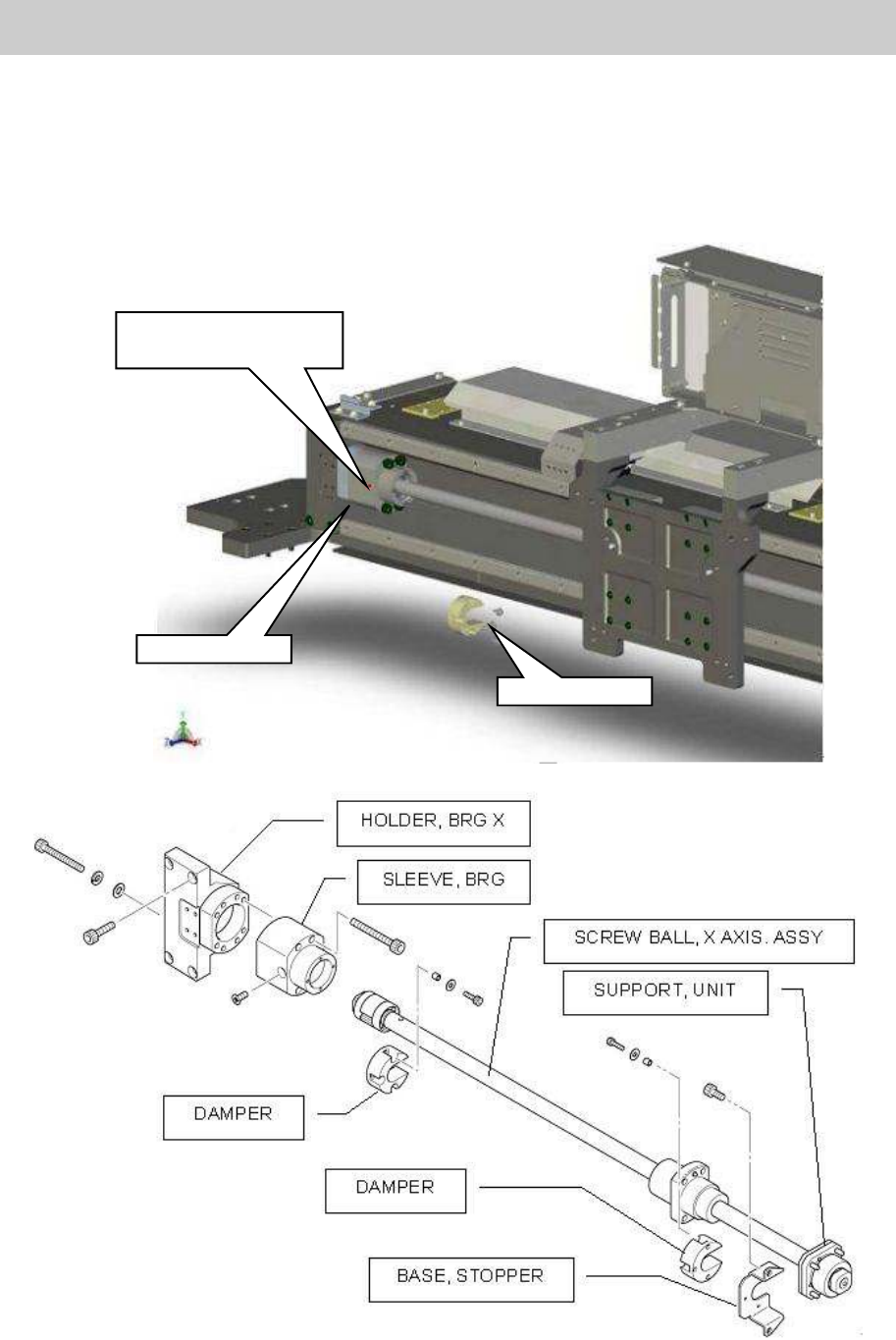
2. Remove the four bolts (M5*16 / BOLT HEX, SOCKET HEAD/ See No.26 in Figure 1) of the screw
nut mounted at the center of the ball screw.
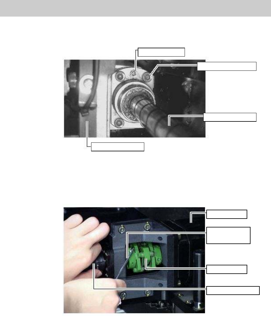
Figure 5
3. Remove the four bolts (M4*14) of the SUPPORT UNIT (See No.20 in Figure 1).
4. Loosen the two bolts at the slotted part (on the screw side) of the coupling (See No.2 in Figure 1).
Figure 6
5. Remove the SUPPOT UNIT (No.20 in Figure 1) from the ball screw, then remove the ball screw
from the X-axis frame.
Grease nipple
Fixing bolts (Qty: 4)
Ball screw of X-axis
HOLDER, HEAD
X-axis motor
Hex wrench
(Size 3)
Coupling
X-axis ball screw
Service Engineer
Service Information
SI0802008E-000= YG series: Replacement procedure for ball screws of each axis
8/65
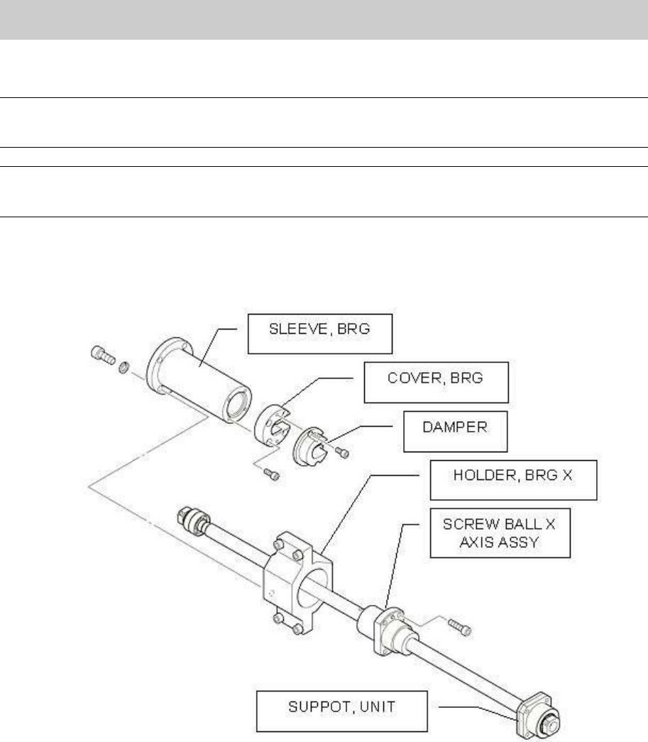
1.3. How to assemble the ball screw Assy. and other attached components
Caution:
Stick the shims to where they were before with the grease. Please be careful not to lose them when
assembling the parts.
Note:
Please make sure to ship the ball screw as a Sub-Assy.
Assemble the parts taking the replaced ball screw Assy. as a model.
1. Set the Ball screw Assy. to the HOLDER MOTOR X.
After putting the sub-assembled ball screw Assy through the HOLDER HEAD and the HOLDER
BRG X, set the ball screw (on the motor side) in the SUPOPRT UNIT
Figure 7