YAMAHA-YG系列 换螺杆指导书.pdf - 第20页
Service Engineer Service I nformati on SI080 2008 E-000 = YG series: Replacement proc edure for ball screws of each axis 20/65 2.3. How to assembl e the ball screw A ssy . and other attached component s Caution: Stick th…
Service Engineer
Service Information
SI0802008E-000= YG series: Replacement procedure for ball screws of each axis
19/65
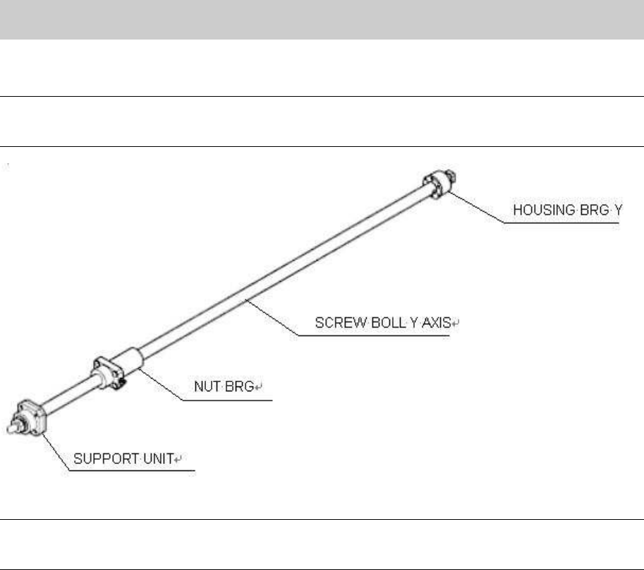
2.2.1. Sub-assembly
Note:
Please ship the ball screw as a Sub-Assy.
Assemble the parts taking the replaced Ball screw Assy. as a model.
Figure 23
Caution:
When you assemble the parts by yourself without using the sub-Assy., please make sure to check and
adjust the center position of the bearing.
1. Assemble the parts at the dead end side of the ball screw. (Bearing, seal, shim and housing)
2. Mount the SUPPORT UNIT assembled in procedure 1 on the ball screw on the motor side, and fix
it by tightening the LOCK NUT. Then tighten the set screw on a corner of the LOCK NUT and
make a mark with a marker pen.
3. Set the stopper to the ball screw.
Service Engineer
Service Information
SI0802008E-000= YG series: Replacement procedure for ball screws of each axis
20/65
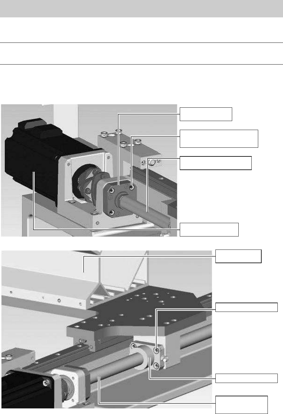
2.3. How to assemble the ball screw Assy. and other attached components
Caution:
Stick the shims to where they were before with the grease. Please be careful not to lose them when
assembling the parts.
1. Set the ball screw sub-Assy. to the HOLDER NUT Y AXIS.
2. Insert the SUPOPRT UNIT into the HOLDER MOTOR Y and fix it by fully tightening the four bolts
(M4*14).
Figure 24
Figure 25
SUPPORT UNIT
Fixing bolt for the
SUPPORT UNIT (Qty:4)
SCREW BALL Y AXIS
Motor for the Y-axis
X-axis frame
Fixing bolts (Qty:4)
Y-axis nut bearing
SCREW BALL Y
AXIS
Service Engineer
Service Information
SI0802008E-000= YG series: Replacement procedure for ball screws of each axis
21/65
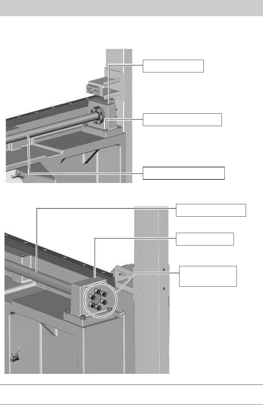
When mounting the ball screw of YGD, YG88 and YG100 models.
3. Insert the HOUSING BRG. Y into the HOLDER BRG. Y, and fix the HOUSING BRG Y
temporarily with the four fixing bolts (M5*14).
Figure 26
4. Temporarily tighten the six bolts (M4*30) of the coil springs that pull the ball screw with fingers.
Figure 27
Caution:
If a shim plate was put between the HOLDER BRG Y and the Y-axis frame before replacement, put the
shim back to where it was when assembling them.
HOLDER, BRG. Y
Bolts to fix the holder (Qty:4)
SCREW BALL Y AXIS
SCREW BALL Y AXIS
HOLDER, BRG. Y
Bolts for the coil
springs of the
Y-axis ball screw