YAMAHA-YG系列 换螺杆指导书.pdf - 第41页
Service Engineer Service I nformati on SI080 2008 E-000 = YG series: Replacement proc edure for ball screws of each axis 41/65 4. Remove the pully of the ball screw to be replaced. Loosen the two set screws that fix the …
Service Engineer
Service Information
SI0802008E-000= YG series: Replacement procedure for ball screws of each axis
40/65
4.2. How to remove the ball screw
1. Turn off the machine before replacing the ball screw.
Check the surrounding area for safety and click on the [OFF] button on the screen. Turn off the
machine following the instruction on the screen.
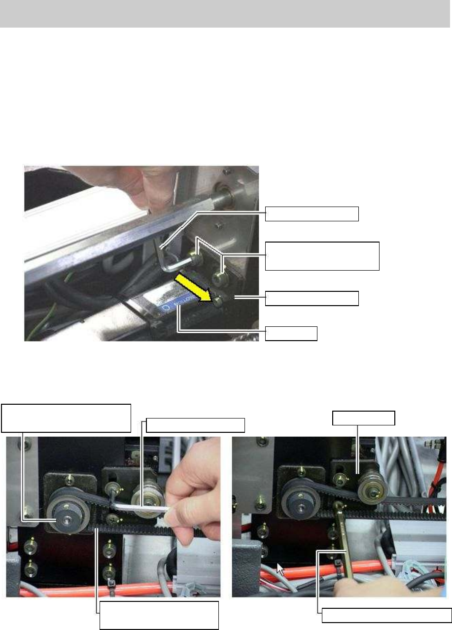
2. Remove the timing belt between the motor and the screw.
Loosen the two bolts that fix the motor bracket with a hex wrench (Size 4) to loosen the belt
tensioner (*move it to the direction that the arrow indicates as shown in
Figure 54
) in order to
remove the timing belt.
Figure 54
3. Loosen the two bolts that fix the belt tensioner (on the right and left) with a hex wrench (Size 4)
and a phillips-head screwdriver in order to remove the timing belt.
Figure 55
Hex wrench (Size 4)
Fixing bolts for the
motor bracket (M5)
Motor bracket
W-axis
The pulley for synchronizing
the W-axis movement
Hex wrench (Size 4)
Belt tensioner
Phillips-head screw driver
The belt for synchronizing
the W-axis movement
Service Engineer
Service Information
SI0802008E-000= YG series: Replacement procedure for ball screws of each axis
41/65
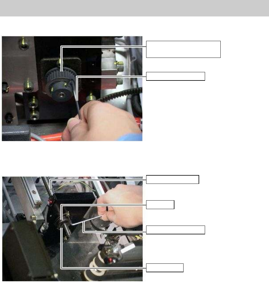
4. Remove the pully of the ball screw to be replaced.
Loosen the two set screws that fix the pulley with a hex wrench (Size 2) and remove the pulley.
Figure 56
5. Remove the two bolts that fix the bearing inside the reference side conveyor frame with a hex
wrench (Size 3), and remove the bearing and the spacer ring.
Figure 57
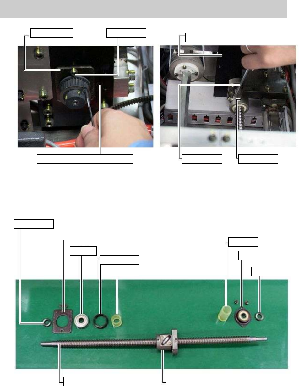
6. Remove the dead-end bearing that supports the ball screw to be replaced.
1) Remove the two bolts of the plate that secures the bearing and is located outside the frame
of the movable conveyor with a hex wrench (Size 3), and remove the plate, the spacer ring
and the bearing.
2) Remove the four bolts that fix the nut bearing with a hex wrench (Size 4).
Pulley for synchronizing the
W-axis movement
Hex wrench (Size 2)
W-axis ball screw
Bearing
Hex wrench (Size 3)
Spacer ring
Service Engineer
Service Information
SI0802008E-000= YG series: Replacement procedure for ball screws of each axis
42/65
Figure 58
7. Remove the ball screw to be replaced.
Remove the ball screw from inside the conveyor and remove the bearing on the motor side of the
ball screw.
Figure 59
Bearing plate
Fixing bolt
Driven-side conveyor
Reference side conveyor stand
Hex wrench
Nut bearing
Spacer collar
Bearing plate
Bearing
Spacer collar
Damper
Damper
Spacer collar
Bearing unit
Ball screw
Nut bearing