YAMAHA-YG系列 换螺杆指导书.pdf - 第36页
Service Engineer Service I nformati on SI080 2008 E-000 = YG series: Replacement proc edure for ball screws of each axis 36/65 2. Attach the dial stand on the pl ate. Figure 49 Press the dial gauge against the top surfac…
Service Engineer
Service Information
SI0802008E-000= YG series: Replacement procedure for ball screws of each axis
35/65
3.2.1. How to adjust the flatness of the pushup plate
If the pushup pins do not evenly touch the undersurface of the board, the components may not be
populated on the board properly. In this case, the deviation from flatness of the pushup plate needs to
be corrected.
Also, as the deviation occurs due to the replacement of the PU-axis motor, the flatness needs to be
adjusted as well.
Note:
Please make sure that there is no warpage of the reference board when adjusting the flatness of the
pushup plate.
Required tools
- Hex wrench set
- Spanner (8-17mm)
- Flathead screwdriver
- Dial gauge (1/100mm)
- Magnet stand
* Time required for adjustment: Approx. 2 hours
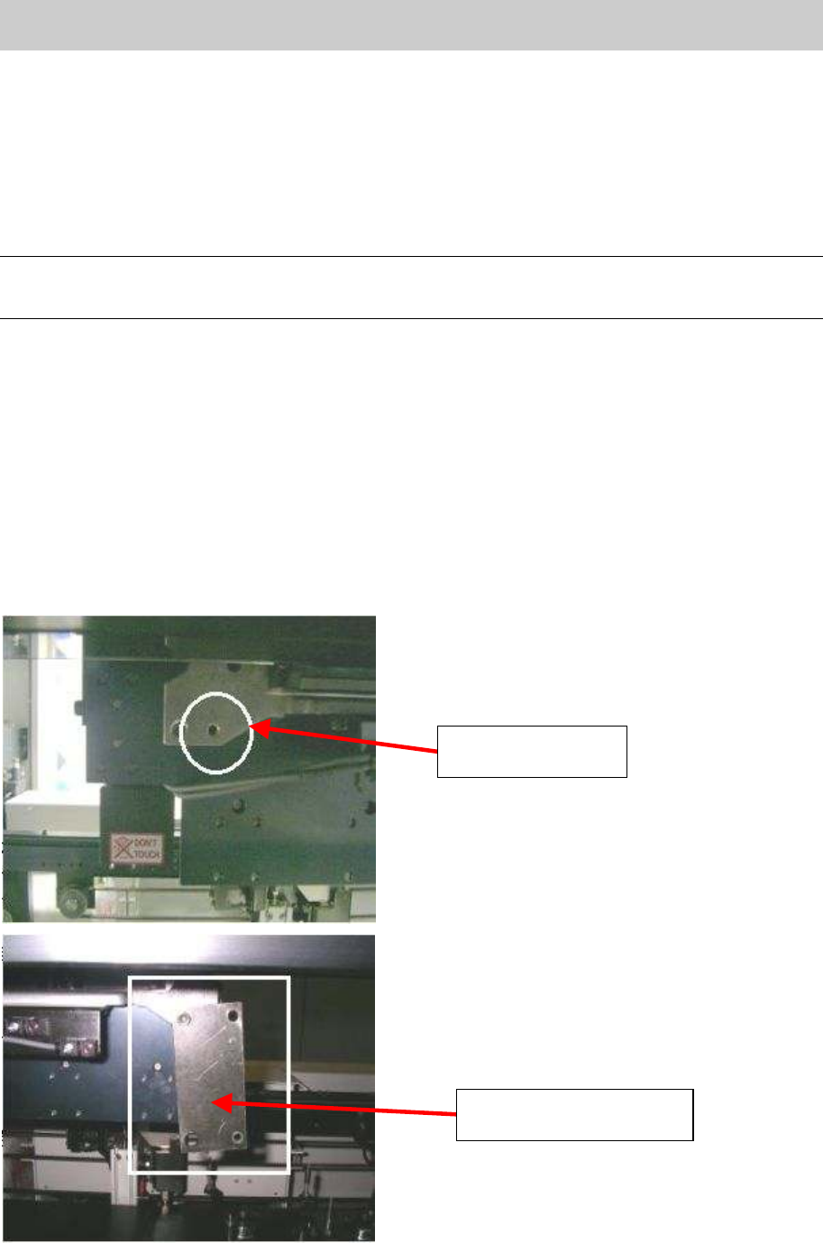
3.2.1.1. Check the deviation from flatness of the pushup plate against the X-axis
1. Mount the plate used for attaching the magnet stand to the backside of the head.
Figure 48
The hole for
mounting the plate
The plate mounted to the
backside of the head
Service Engineer
Service Information
SI0802008E-000= YG series: Replacement procedure for ball screws of each axis
36/65
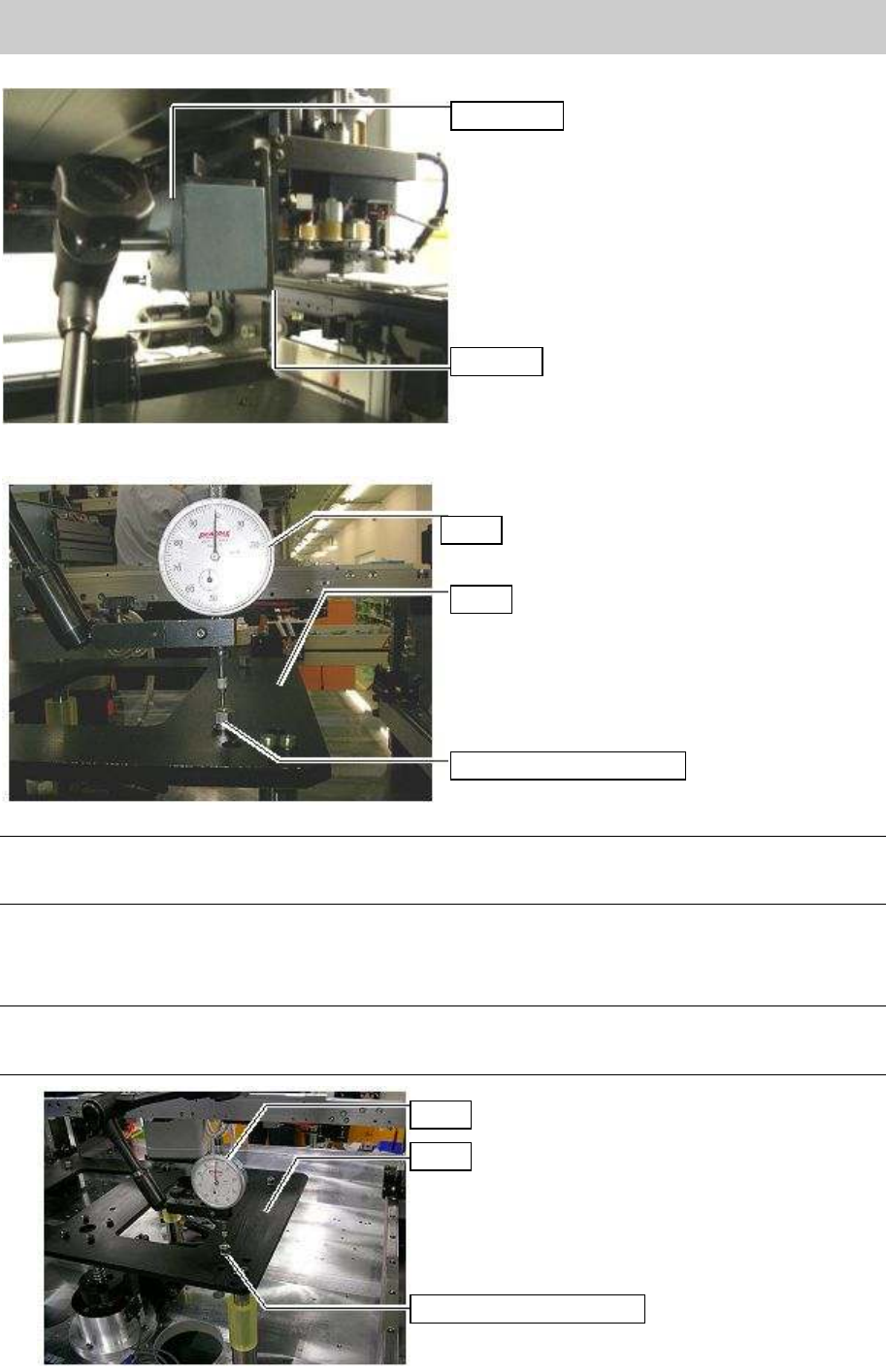
2. Attach the dial stand on the plate.
Figure 49
Press the dial gauge against the top surface of the spacer nut of the stay.
Figure 50
Note:
Press the gauge (1/100mm scale) against the top surface of the spacer to let the needle go around
once. This is where the most correct measurement can be obtained.
3. ^Move the camera and measure the height of the top surface of the spacer nuts (4-8 points).
If the measured height exceeds the specification, please follow the procedure in “3.2.1.2. Adjust
the parallelism (Mechanical adjustment).
Note:
The reference value of the flatness (height) is within 0.15mm. Please adjust the height so that the
value falls within the specification.
Figure 51
Dial stand
Plate
Dial
Stay
Spacer nut for the stay
Dial
Stay
Spacer nut for the stay
Service Engineer
Service Information
SI0802008E-000= YG series: Replacement procedure for ball screws of each axis
37/65
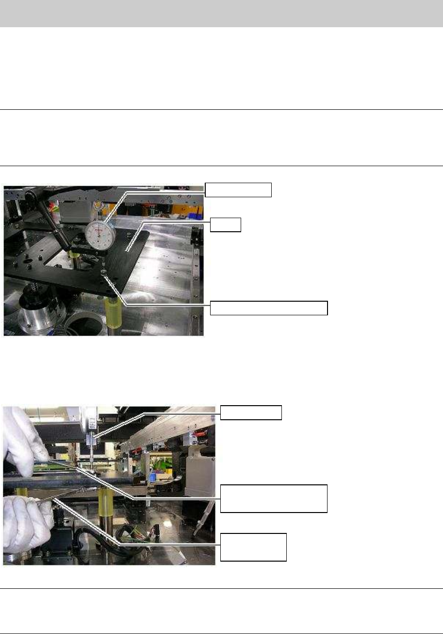
3.2.1.2. Adjust the parallelism (Mechanical adjustment)
1. Set the dial gauge to the top surface of the spacer that is considerably higher or lower compare to
other spacers.
Loosen the U-nut that is securing the stay spacer, and then adjust the height of the spacer while
checking the height with the dial gauge.
Note:
The stay used for YG88 and YG100 is supported with one ball screw and three ball guides.
(Single pushup)
The stay used for YG88R and YG100R is supported with the two ball screws and two ball guides.
(Single pushup)
Figure 52
2. Adjust the height of the spacer
Loosen the U-Nut of the bolt securing the spacer temporarily. Rotate the bolt in order to adjust the
height while checking the dial gauge.
Figure 53
Note:
Adjust the highest spacer and lowest spacer measured in “3.2.1.1. Check the deviation from flatness of
the pushup plate against the X-axis, Procedure 3”). Please adjust the height of the spacers using the
dial gauge so that the height difference is to be within 0.15mm.
Dial gauge
Stay
Spacer nut for the stay
Spanner on the
plate spacer nut side
Spanner
U-nut side
Dial gauge