YAMAHA-YG系列 换螺杆指导书.pdf - 第3页
Service Engineer Service I nformati on SI080 2008 E-000 = YG series: Replacement proc edure for ball screws of each axis 3/65 1. How to r eplace a ball screw of X -axis <Overview > Though the com ponent parts that …

Service Engineer
Service Information
SI0802008E-000= YG series: Replacement procedure for ball screws of each axis
2/65
4.3. How to mount the new bearing.................................................................................................... 43
4.4. Adjustment after replacing the ball screw ................................................................................... 45
5. Adjustment ......................................................................................................................................... 46
5.1. Start up the “Asjutment utility” ..................................................................................................... 46
5.2. Initial Setting (How to switch the mode while the “Adjustment Utility” is running) ....................... 47
5.3. Useful functions (Help)................................................................................................................ 49
5.4. Machine reference for each axis.................................................................................................50
5.4.1. Check the machine reference for each axis......................................................................... 50
5.4.2. Adjust the machine reference............................................................................................... 51
5.4.3. Check and adjust the Y2-axis dual offset.............................................................................52
5.5. How to set the reference coordinate ...........................................................................................53
5.5.1. Set the reference coordinate before replacement of the Axis .............................................. 53
5.5.2. Adjust the axis position to the reference coordinate after replacing the ball screw.............. 54
5.6. Adjustment of the soft limit.......................................................................................................... 55
5.6.1. Adjustment of the soft limit ...................................................................................................56
5.6.2. Check the soft limit ............................................................................................................... 57
5.7. Adjustment of the soft limit for YG300 model <Calib Sm Ver.3.02R1.000 or later> ................... 58
5.8. Check the peak current (with the “Servo” utility) ......................................................................... 60
5.9. The belt tension specifications .................................................................................................... 63

Service Engineer
Service Information
SI0802008E-000= YG series: Replacement procedure for ball screws of each axis
3/65
1. How to replace a ball screw of X-axis
<Overview>
Though the component parts that make up the ball screw Assy. vary depends on the models, there are
three main types of them.
This document describes the replacement method of the ball screws by dividing them into three types
depends on the models as follows:
- YGD
- YG88, YG100, YG200 (L), YG300
- YG88R, YG100R
Required tools
- Phillips-head screw driver (Standard type)
- Hex wrench set
- Special T-shape hex wrench (Size 5) or ratchet wrench set
- Nipper
- Some cable ties (150mm, 250mm)
- Marker pen (Used after checking if the screws are tightened properly)
- New ball screw for X-axis (Sub-Assy. Part)
1.1. Work to be done before replacement
The coordinates of the machine deviate due to the replacement of the parts. Therefore, some works
need to be done in order to restore the coordinates in the simple method.
Also, in case the ball screw is broken or the problem such as seizure occurs, the works before the
replacement cannot be performed and various adjustments need to be performed.
Caution:
Please make sure to do the necessary work before replacement. Otherwise, you will need to perform
all the adjustment, which requires a great deal of time later on.
<Works to be done>
- Check the machine reference of each axis
- Set the reference coordinate before replacing the ball screw.
* Please refer to the relevant section in “5. Adjustment”.
Service Engineer
Service Information
SI0802008E-000= YG series: Replacement procedure for ball screws of each axis
4/65
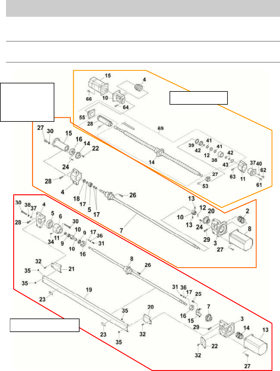
1.2. How to remove the ball screw of X-axis
Caution:
As some removed parts may contain shims, please be careful not to lose them. Also, please note
down the places where the shims were set.
Figure 1
YGD & Xg
YG100
YG88
YG200(L)
YG300
YG100R & YG88R