YAMAHA-YG系列 换螺杆指导书.pdf - 第16页
Service Engineer Service I nformati on SI080 2008 E-000 = YG series: Replacement proc edure for ball screws of each axis 16/65 Wh en removing t he ball screw of Y GD, YG88 and YG100 models. 1. Remove the six bolts (M4*…
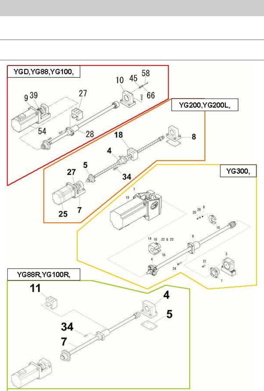
Service Engineer
Service Information
SI0802008E-000= YG series: Replacement procedure for ball screws of each axis
15/65
2.2. How to remove the ball screw of Y1,2-axis
Caution:
As some removed parts may contain shims, please be careful not to lose them. Also, please note
down the places where the shims were set.
Figure 16
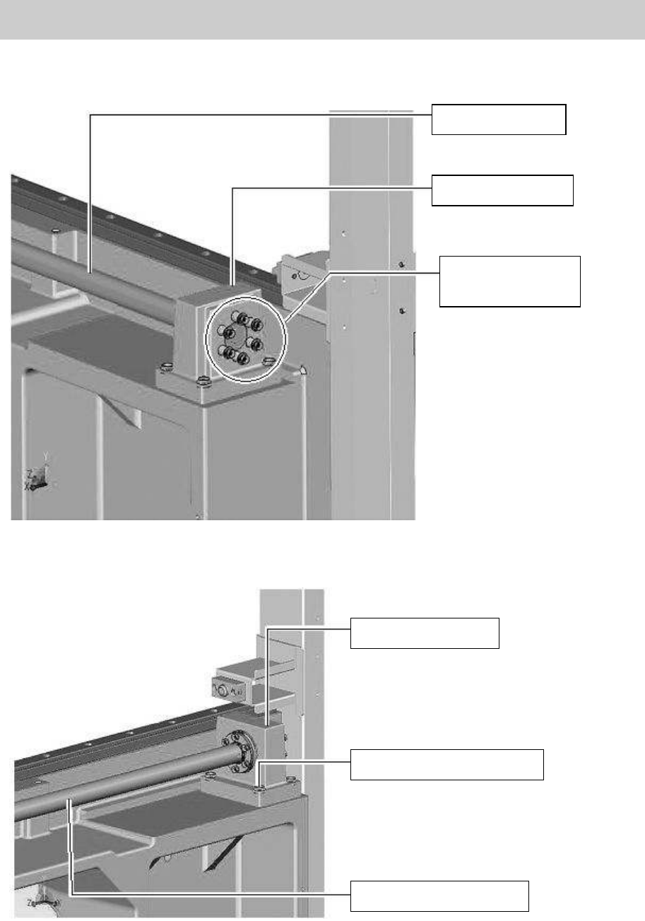
Service Engineer
Service Information
SI0802008E-000= YG series: Replacement procedure for ball screws of each axis
16/65
When removing the ball screw of YGD, YG88 and YG100 models.
1. Remove the six bolts (M4*30) of the coil springs that pull the ball screw.
Figure 17
2. Remove the four bolts that fix the HOLDER BRG Y (No.10 in Figure 16).
Figure 18
Ball screw of Y-axis
HOLDER, BRG. Y
Bolts for the coil
springs of the
Y-axis ball screw
HOLDER, BRG. Y
Bolts to fix the holder (Qty:4)
The ball screw of Y-axis
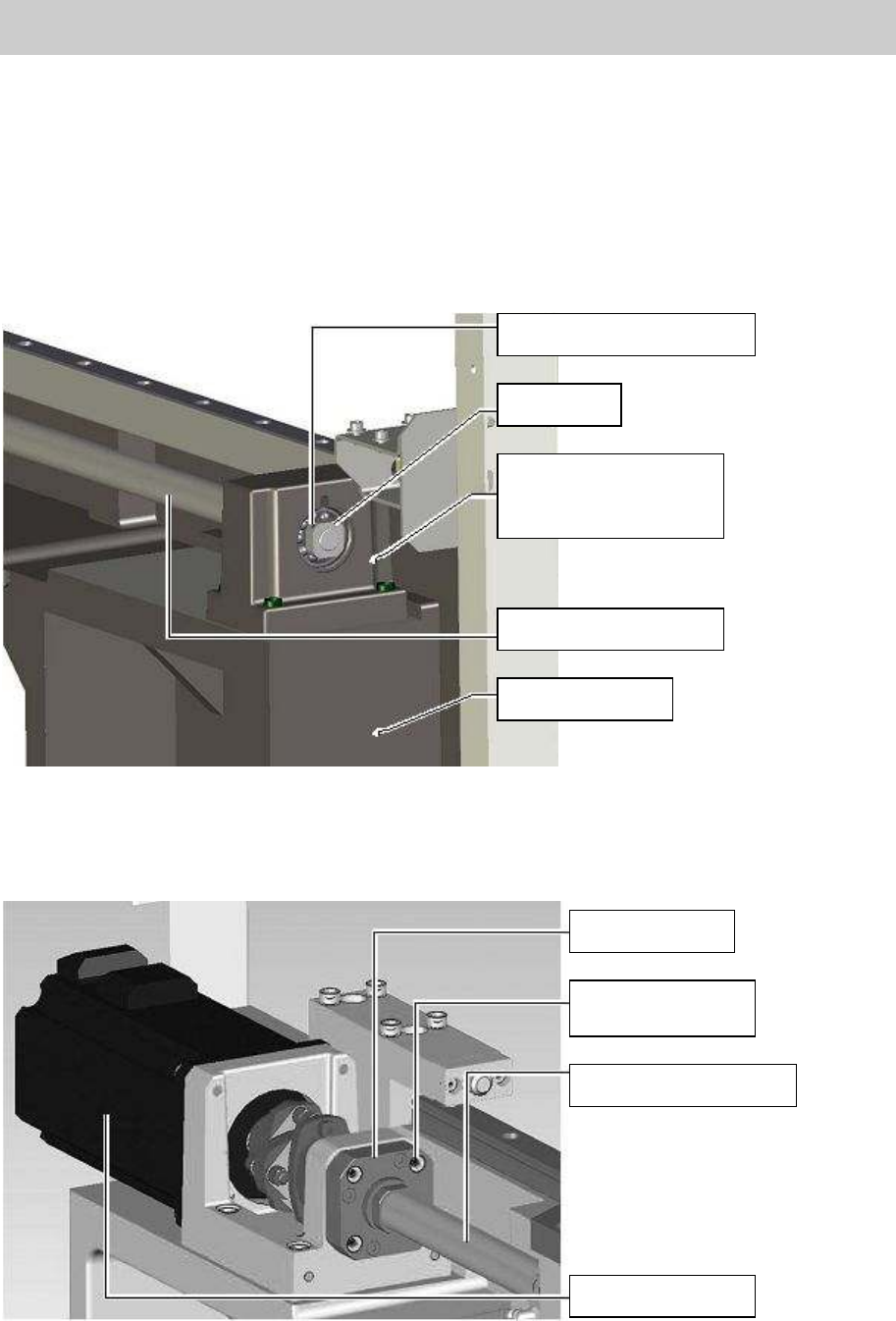
Service Engineer
Service Information
SI0802008E-000= YG series: Replacement procedure for ball screws of each axis
17/65
When removing the ball screws of YG88R, YG100R, YG200, YG200L and YG300 models.
1. Remove the bearing on the dead end side of the SCREW BALL Y AXIS.
1) Loosen the set screw for anti-backlash on a corner of the LOCK NUT by rotating it about 360
degrees with a hex wrench.
2) Loosen the LOCK NUT while inserting a hex wrench into a hole (for anti-rotation) on the SCREW
BALL Y AXIS.
3) Remove the LOCK NUT from the SCREW BALL Y AXIS and remove the whole bearing unit.
Figure 19
The following procedure is common to all the models.
2. Remove the four bolts (M4*14) that fix the SUPPORT UNIT.
Figure 20
Setscrew for anti-backlash
LOCK NUT
HOLDER, BRG. Y
*Please do not remove
this part.
SCREW BALL Y AXIS
FRAME R, Y AXIS
SUPPORT UNIT
Fixing bolt for the
SUPPORT UNIT
SCREW BALL Y AXIS
Motor for the Y-axis