YAMAHA-YG系列 换螺杆指导书.pdf - 第17页
Service Engineer Service I nformati on SI080 2008 E-000 = YG series: Replacement proc edure for ball screws of each axis 17/65 Wh en removing t he ball screws of Y G88R, YG100R, YG 200, YG200L and Y G300 models. 1. Rem…
Service Engineer
Service Information
SI0802008E-000= YG series: Replacement procedure for ball screws of each axis
16/65
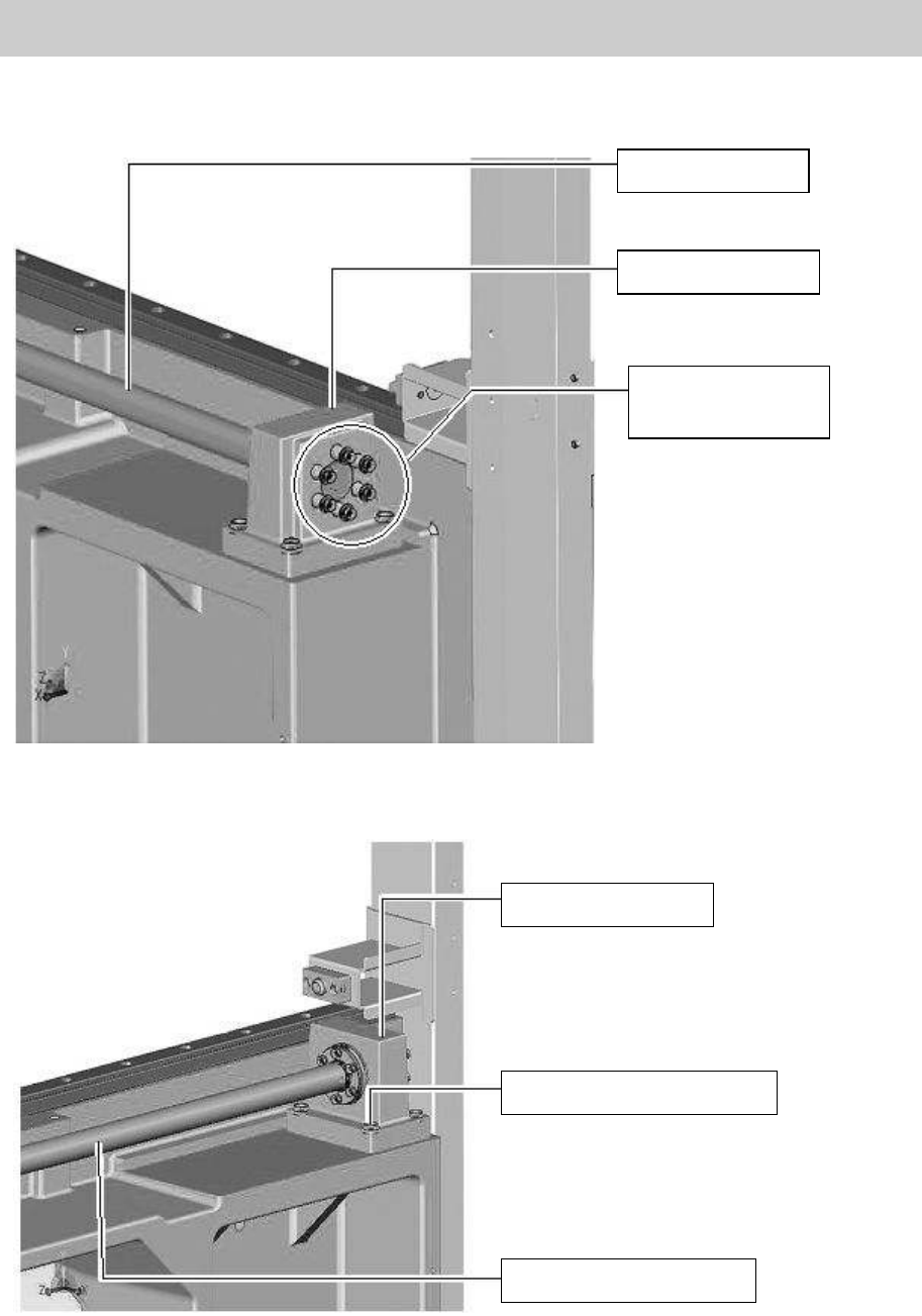
When removing the ball screw of YGD, YG88 and YG100 models.
1. Remove the six bolts (M4*30) of the coil springs that pull the ball screw.
Figure 17
2. Remove the four bolts that fix the HOLDER BRG Y (No.10 in Figure 16).
Figure 18
Ball screw of Y-axis
HOLDER, BRG. Y
Bolts for the coil
springs of the
Y-axis ball screw
HOLDER, BRG. Y
Bolts to fix the holder (Qty:4)
The ball screw of Y-axis
Service Engineer
Service Information
SI0802008E-000= YG series: Replacement procedure for ball screws of each axis
17/65
When removing the ball screws of YG88R, YG100R, YG200, YG200L and YG300 models.
1. Remove the bearing on the dead end side of the SCREW BALL Y AXIS.
1) Loosen the set screw for anti-backlash on a corner of the LOCK NUT by rotating it about 360
degrees with a hex wrench.
2) Loosen the LOCK NUT while inserting a hex wrench into a hole (for anti-rotation) on the SCREW
BALL Y AXIS.
3) Remove the LOCK NUT from the SCREW BALL Y AXIS and remove the whole bearing unit.
Figure 19
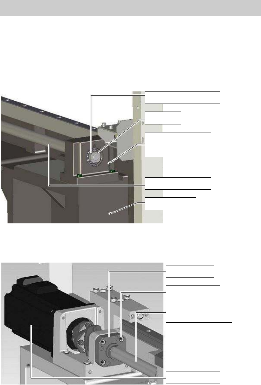
The following procedure is common to all the models.
2. Remove the four bolts (M4*14) that fix the SUPPORT UNIT.
Figure 20
Setscrew for anti-backlash
LOCK NUT
HOLDER, BRG. Y
*Please do not remove
this part.
SCREW BALL Y AXIS
FRAME R, Y AXIS
SUPPORT UNIT
Fixing bolt for the
SUPPORT UNIT
SCREW BALL Y AXIS
Motor for the Y-axis
Service Engineer
Service Information
SI0802008E-000= YG series: Replacement procedure for ball screws of each axis
18/65
3. Loosen the two bolts at the slotted part of the coupling on the ball screw side.
Figure 21
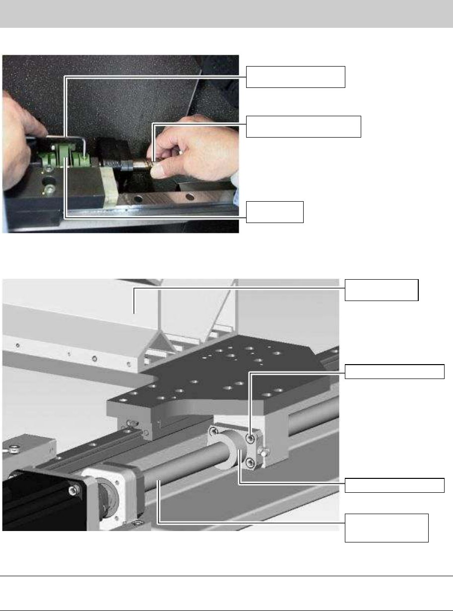
4. Remove the bolts that fix the nut bearing located under the X-axis frame.
Figure 22
5. Slowly move the X-axis frame backwards by hand ino order to remove the ball screw.
Note:
The X-axis frame needs to be moved to the concave part of the Y-axis frame in order to remove the
ball screw.
Hex wrench (Size 3)
SCREW BALL Y AXIS
Coupling
X-axis frame
Fixing bolts (Qty:4)
Y-axis nut bearing
SCREW BALL Y
AXIS