YAMAHA-YG系列 换螺杆指导书.pdf - 第12页
Service Engineer Service I nformati on SI080 2008 E-000 = YG series: Replacement proc edure for ball screws of each axis 12/65 1.4. Centering of the axis * The follo wing procedures are common to all th e models. 1.4.1. …
Service Engineer
Service Information
SI0802008E-000= YG series: Replacement procedure for ball screws of each axis
11/65
* The following procedures are common to all the models.
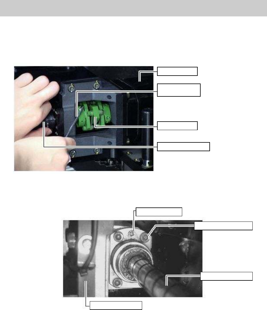
4. Temporarily tighten the coupling.
Temporarily tighten one of the two bolts at the slotted part (No.2 in Figure 1) on the ball screw side
of the coupling.
Figure 12
5. Temporarily fix the screw nut mounted at the center of the ball screw with the four bolts (M5*16/
See No.26 in Figure 1).
Figure 13
Grease nipple
Fixing bolts (Qty: 4)
Ball screw of X-axis
HOLDER, HEAD
X-axis motor
Hex wrench
(Size 3)
Coupling
X-axis ball screw
Service Engineer
Service Information
SI0802008E-000= YG series: Replacement procedure for ball screws of each axis
12/65
1.4. Centering of the axis
* The following procedures are common to all the models.
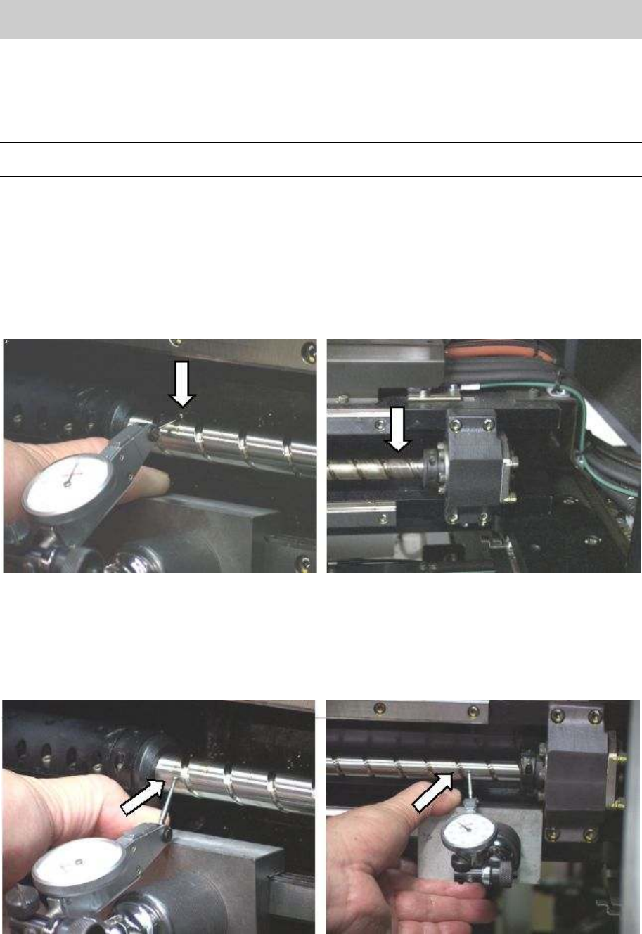
1.4.1. Perform centering of the X-axis ball screw
Note:
Please perform centering with reference to the height of the center of the ball screw on the motor side.
1. Set the tool (plate) for centering to the upper GUIDE SET of the X axis frame.
2. Attach a dial gauge on the stand base on the guide set.
3. Put the dial gauge at the point near the SUPPORT UNIT on the ball screw and perform zero
setting.
4. Put the dial gauge at the point near the HOLDER BRG. X on the ball screw and adjust the height of
the SLEEVE BRG by moving it up and down untill the dial gauge indicates 0 and fix it temporarily
by tightening the fixing bolts.
Figure 14
5. Put the dial gauge at the point near the SUPPORT UNIT on the ball screw and perfrom zero
setting.
6. Put the dial gauge at the point near the HOLDER BRG. X on the ball screw, and adjust the position
of SLEEVE BRG by moving it from side to side until the dial gauge indicates 0, then temporarily
tighten the fixing bolts.
Figure 15
7. Repeat the procedure from 3 through 6 to adjust the deviation of the center of the ball screw so
that it falls within +-0.01mm. Then fully tighten the bolts.

Service Engineer
Service Information
SI0802008E-000= YG series: Replacement procedure for ball screws of each axis
13/65
1.4.2. Adjustment after replacing the ball screw
The coordinates of the machine deviate due to the replacement of the parts. Therefore, some works
need to be done in order to restore the coordinates in the simple method.
Caution:
Please make sure to do the necessary work before replacement. Otherwise, you will need to perform
all the adjustment, which requires a great deal of time later on.
<Works to be done>
• Adjust the machien reference.
• Adjust to the reference coordinate after the replacement of the ball screw.
• Check the peak current (With the Servo utility).
* Please refer to the relevant section in “5. Adjustment”.
• Set the ball screw cover. (*Only for the YG88R and YG100R models.)
Set the both side of the pieces of the cover first, then set the center part.
Check if the bolts are tightened properly
1. Press the [Emergency stop] button and check the surrounding area for safety.
2. Check the bolts removed for replacement or loosened are tightened properly.
Check if the bolts are tightened with the appropriate hex wrench and make a mark on the
bolts with the marker pen.
Other items to be checked and done
1. Check if there are any tools used for replacement left in the machine.
2. Check if there are any pieces of cut off cable tie left in the machine.
3. Make sure that all the harnesses are secured properly, and no axes interfere with anything
when they move.
Caution:
Please do not use an air gun for cleaning inside the machine. The blown away dusts may stick to the
moving parts of the axes, which causes the serious problem to the machine.
4. Get ready for the production activity
Put back all the removed parts such as feeders and other supplying equipments to the
original position.
1.5. Necessary adjustment
Note:
Please refer to the relevant section in “YG300 CalibSm Adjustment Manual” for performing the
following adjustment.
• Check and adjust the soft limit of the X-axis
• Check and adjust the coordinate of the ANC nozzle station.
• Check if the ANC consecutive nozzle change works properly after adjusting the coordinate of the
nozzle station.
• Check and adjust the coordinate of the blow station.
* Please use an actual board and perform mounting test.
If the mounting accuracy is not enough, please perform FAMF adjustment.