YAMAHA-YG系列 换螺杆指导书.pdf - 第31页
Service Engineer Service I nformati on SI080 2008 E-000 = YG series: Replacement proc edure for ball screws of each axis 31/65 3.2. How to m ount the new ball screw 1. Insert the new ball screw into the rem oved unit fro…
Service Engineer
Service Information
SI0802008E-000= YG series: Replacement procedure for ball screws of each axis
30/65
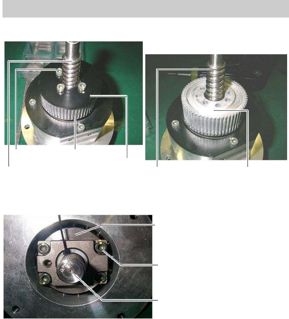
6. Remove the four bolts that fix the flange on the axis unit that includes the ball screw removed in
the procedure 5 with a hex wrench, then remove the flange and the pulley from the unit.
Figure 39
7. Remove the bolts attached to the housing nut which is at the bottom of the ball screw in order to
remove the ball screw from the unit.
Figure 40
Bolts (Qty:4)
Ball screw
Pulley
Flange
Ball screw
Pulley
Nut housing
Fixing bolt
Ball screw
Service Engineer
Service Information
SI0802008E-000= YG series: Replacement procedure for ball screws of each axis
31/65
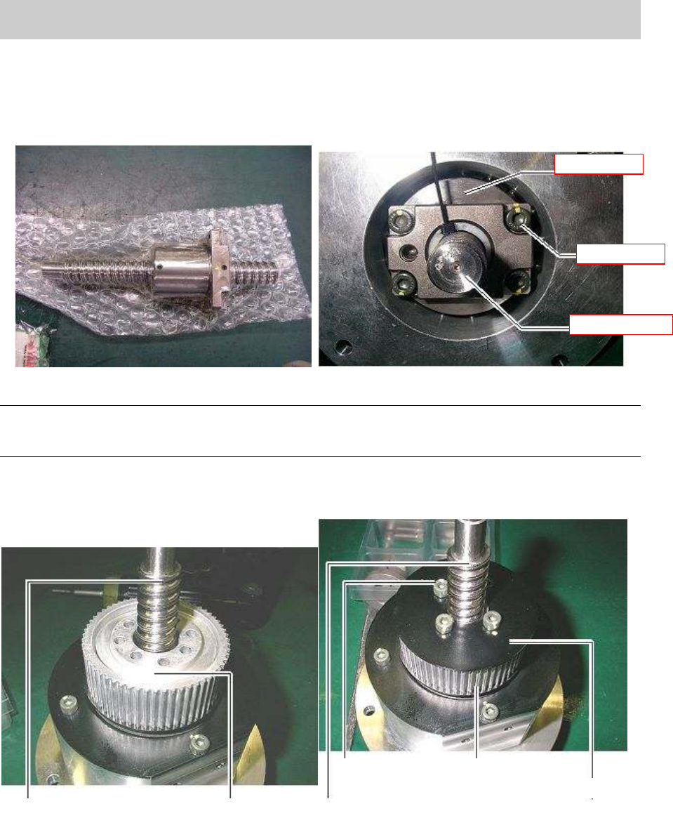
3.2. How to mount the new ball screw
1. Insert the new ball screw into the removed unit from the bottom side and fix it to the nut housing
with four bolts using a hex wrench.
Figure 41
Caution:
If you separate the nut part and the scew part of the ball screw, the balls in the grooves of ball screw
fall.
2. Mount the pulley and the flange on the upper part of the unit and fix them with four bolts using a
hex wrench.
Figure 42
Nut housing
Fixing bolt
Ball screw
Bolts (Qty:4)
Ball screw
Pulley
Flange
Ball screw
Pulley
Service Engineer
Service Information
SI0802008E-000= YG series: Replacement procedure for ball screws of each axis
32/65
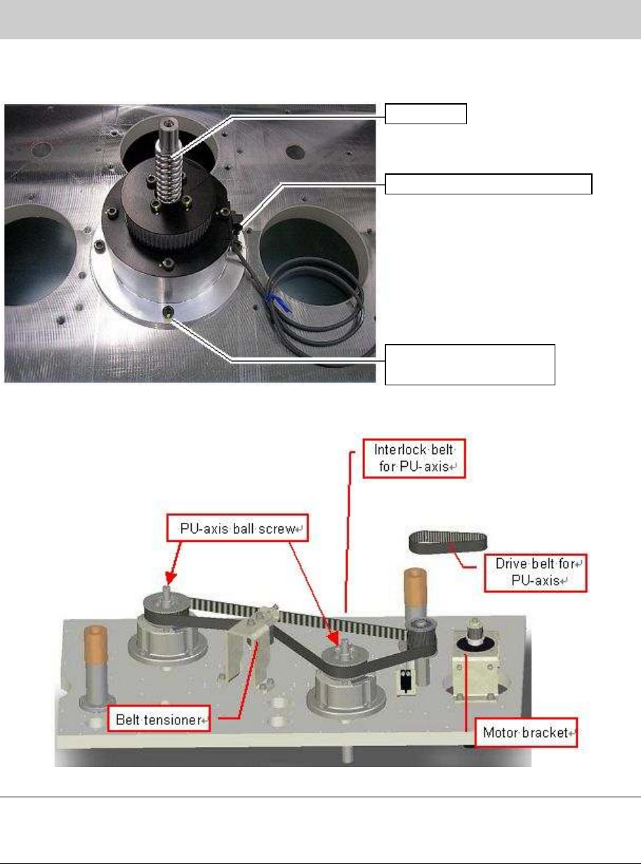
3. Set the axis unit on the base and fix it to the base with four bolts.
[YG88 & YG100]
Figure 43
[YG88R & YG100R]
Figure 44
Note:
YG88R and YG100R machines have two ball screws. As the ball screws are driven via inter midiate
shaft, two types of belts are used. One is for driving the ball screws and the other is for interlocking the
movement of the ball screws.
4. Adjust the belt tension.
Put the belt arount the pulley of the unit and the pully of the motor. (put the belt so that the letters
written on the belt can be read from your side.)
Fully tighten the bolts of the motor bracket while adjusting the tension of the belt.
Connect the connector of the origin sensor and turn on the machine, then perform
Return-to-origin.
Ball screw
Origin sensor for PU-axis
Bolts for fixing the
bearing housing (Qty:4)