YAMAHA-YG系列 换螺杆指导书.pdf - 第37页
Service Engineer Service I nformati on SI080 2008 E-000 = YG series: Replacement proc edure for ball screws of each axis 37/65 3.2.1.2. A djust the parallelism (M echanical adjustmen t) 1. Set the dial ga uge to the top …
Service Engineer
Service Information
SI0802008E-000= YG series: Replacement procedure for ball screws of each axis
36/65
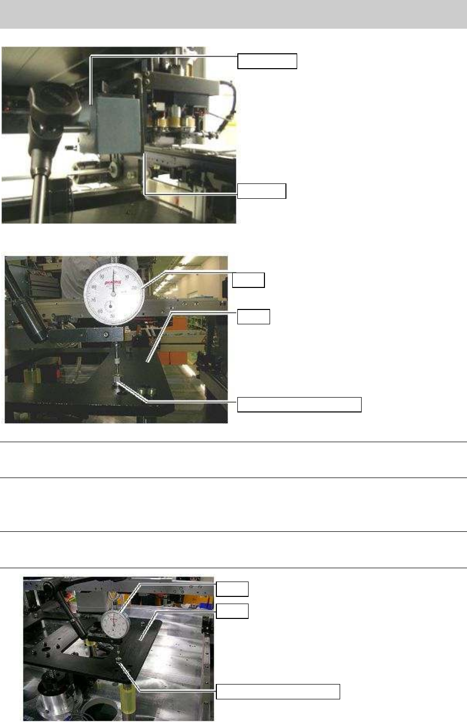
2. Attach the dial stand on the plate.
Figure 49
Press the dial gauge against the top surface of the spacer nut of the stay.
Figure 50
Note:
Press the gauge (1/100mm scale) against the top surface of the spacer to let the needle go around
once. This is where the most correct measurement can be obtained.
3. ^Move the camera and measure the height of the top surface of the spacer nuts (4-8 points).
If the measured height exceeds the specification, please follow the procedure in “3.2.1.2. Adjust
the parallelism (Mechanical adjustment).
Note:
The reference value of the flatness (height) is within 0.15mm. Please adjust the height so that the
value falls within the specification.
Figure 51
Dial stand
Plate
Dial
Stay
Spacer nut for the stay
Dial
Stay
Spacer nut for the stay
Service Engineer
Service Information
SI0802008E-000= YG series: Replacement procedure for ball screws of each axis
37/65
3.2.1.2. Adjust the parallelism (Mechanical adjustment)
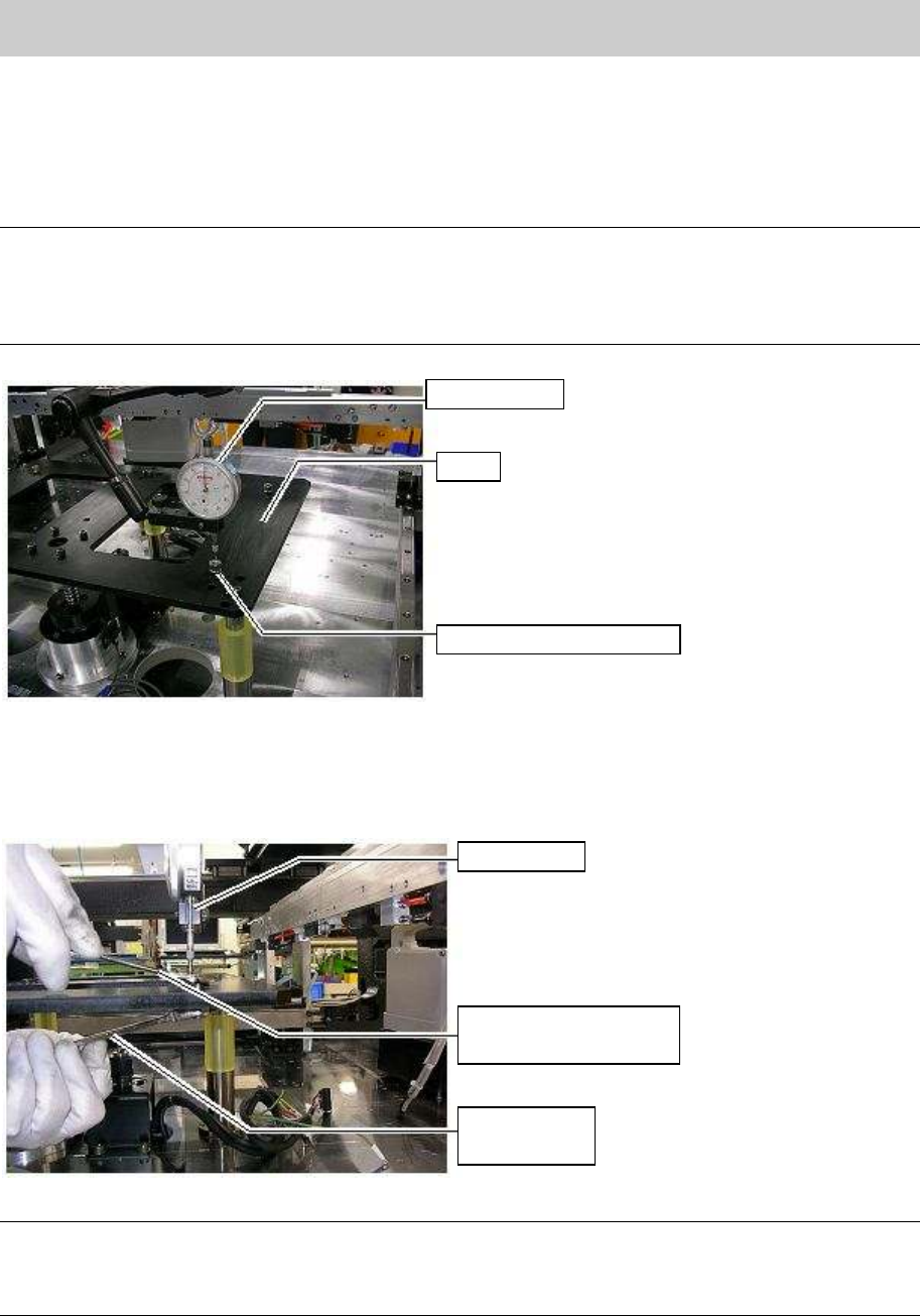
1. Set the dial gauge to the top surface of the spacer that is considerably higher or lower compare to
other spacers.
Loosen the U-nut that is securing the stay spacer, and then adjust the height of the spacer while
checking the height with the dial gauge.
Note:
The stay used for YG88 and YG100 is supported with one ball screw and three ball guides.
(Single pushup)
The stay used for YG88R and YG100R is supported with the two ball screws and two ball guides.
(Single pushup)
Figure 52
2. Adjust the height of the spacer
Loosen the U-Nut of the bolt securing the spacer temporarily. Rotate the bolt in order to adjust the
height while checking the dial gauge.
Figure 53
Note:
Adjust the highest spacer and lowest spacer measured in “3.2.1.1. Check the deviation from flatness of
the pushup plate against the X-axis, Procedure 3”). Please adjust the height of the spacers using the
dial gauge so that the height difference is to be within 0.15mm.
Dial gauge
Stay
Spacer nut for the stay
Spanner on the
plate spacer nut side
Spanner
U-nut side
Dial gauge

Service Engineer
Service Information
SI0802008E-000= YG series: Replacement procedure for ball screws of each axis
38/65
3. Fully tighten the bolt which was loosened temporarily in procedure 2 in order to fix the Plate 1.
Measure the height of the Plate 1 again and if the measured value falls within the specification,
complete the adjustment.
Note:
After adjusting the height of the spacers, if the pushup plate is placed on the spacers and it is not level,
the plate itself may not be flat. In this case, please replace the pushup plate or adjust the height of the
spacers again.
3.3. Adjustment after replacing the axis
The coordinates of the machine deviate due to the replacement of the parts. Therefore, some works
need to be done in order to restore the coordinates in the simple method.
Caution:
Please make sure to do the necessary work before replacement. Otherwise, the interference or
collision of the parts may occur and result in serious damage to the machine during automatic
operation
<Works to be done>
• Adjust the machine reference.
• Adjsut the soft limit of the PU-axis, the height of the initial position, and the initial movement in
Machine setting.
• Check the peak current (With the “Servo utility”).
* Please refer to the relevant section in “5. Adjustment”.
Check if the bolts are tightened properly
1. Press the [Emergency stop] button and check the surrounding area for safety.
2. Check the bolts removed for replacement or loosened are tightened properly.
Check if the bolts are tightened with the appropriate hex wrench and make a mark on the
bolts with the marker pen.
Other items to be checked and done
1. Check if there are any tools used for replacement left in the machine.
2. Check if there are any pieces of cut off cable tie left in the machine.
3. Make sure that all the harnesses are secured properly, and no axes interfere with anything
when they move.
Caution:
Please do not use an air gun for cleaning inside the machine. The blown away dusts may stick to the
moving parts of the axes, which causes the serious problem to the machine.
4. Get ready for the production activity
Put back all the removed parts such as feeders and other supplying equipments to the
original position.