YAMAHA-YG系列 换螺杆指导书.pdf - 第47页
Service Engineer Service I nformati on SI080 2008 E-000 = YG series: Replacement proc edure for ball screws of each axis 47/65 3. Click on the relevant adjustm ent item on the “Adjustm ent” tab. * The m ain menu of the “…
Service Engineer
Service Information
SI0802008E-000= YG series: Replacement procedure for ball screws of each axis
46/65
5. Adjustment
5.1. Start up the “Asjutment utility”
Overview
This utility is designed for the customers to perform a stable production operation with YAMAHA
mounters for a long period. It contains programs for controlling machine performance and adjustment
for maintenance. Please prepare all the necessary tools and equipments beforehand. Also this utility is
intended for users who have participated in an advanced maintenance training session (for
maintenance specialist). Those who have not taken the training are not allowed to use the utility.
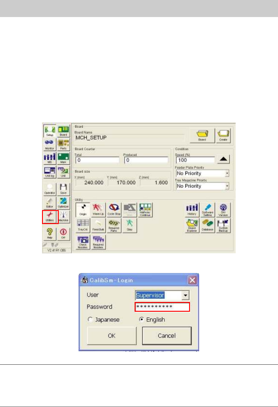
1. Click on the [Utilities] button on the ”Set up” screen.
Figure 64
2. Log in as “Supervisor”.
Figure 65
Caution:
When using this utility, please prepare all the necessary special-purpose adjusting jigs, measuring
instruments, adjusting boards and adjusting parts. Also, please make sure that the users who have
taken the advanced maintenance training always operate the machine. If the person without enough
knowledge performs the adjustment, it could cause a serious problem to the machine. On this account,
the password to log in the adjustment utility is not shown in this manual.
Service Engineer
Service Information
SI0802008E-000= YG series: Replacement procedure for ball screws of each axis
47/65
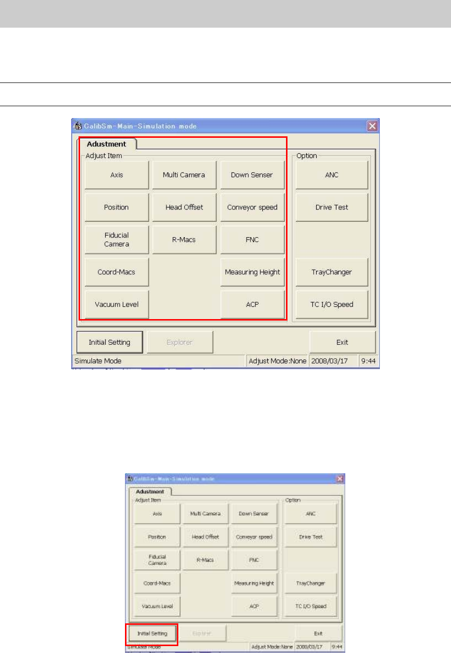
3. Click on the relevant adjustment item on the “Adjustment” tab.
* The main menu of the “Adjustment Utility” (Calib Sm) varies depends on the model and the
application version.
Caution:
The display items on the “Adjustment Utility” screen vary depends on the login user level.
Figure 66
5.2. Initial Setting
(How to switch the mode while the “Adjustment Utility” is running)
1. How to perform initial setting of “Calib Sm”.
Click on the [Initial Setting] button in the “Adjust Item”.
Figure 67
Service Engineer
Service Information
SI0802008E-000= YG series: Replacement procedure for ball screws of each axis
48/65
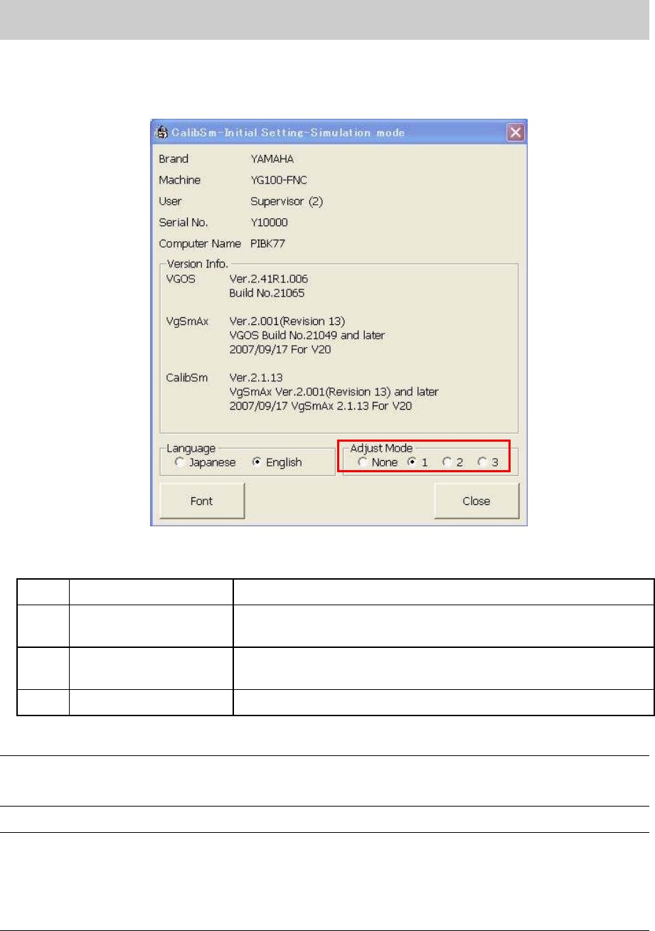
2. Select the mode for adjustment. (If it is set in “VmSpec”, it does not have to be changed.)
Select the radio button “1” from the “Adjust Mode”.
<Initial setting dialog>
Figure 68
<Adjust Mode>
None
Adjust Mode -None Used for Normal production.
1 Adjust Mode 1
Used for adjustment of mounting CHIP components in ACP and
FAMF adjustment.
2 Adjust Mode 2
Used for adjustments of Lead components recognition,
binarization (Black and white) and inversion in FAMF.
3 Adjust Mode 3 Not available
Table 1
Note:
The setting can be switched easily by selecting the radio button of the “Adjust Mode”. However, when
the “Adjustment Utility” is closed, the setting becomes invalid.
Caution:
When performing “ACP adjustment” by using the new ACP board and the CHIP component, please
make sure to switch the adjust mode to “1”.
If the radio button “1” is not selected, when a pick up error occurs, the retry of the head that caused the
error may not be performed. In this case, the head to be adjusted and other head are exchanged and
compensation value cannot be obtained correctly.