YAMAHA-YG系列 换螺杆指导书.pdf - 第55页
Service Engineer Service I nformati on SI080 2008 E-000 = YG series: Replacement proc edure for ball screws of each axis 55/65 5.6. A djustment of the sof t l imit The sof t limit is the safe distance that is s et in ord…
Service Engineer
Service Information
SI0802008E-000= YG series: Replacement procedure for ball screws of each axis
54/65
5.5.2. Adjust the axis position to the reference coordinate after replacing the ball screw
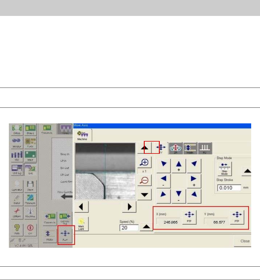
1. Click on the [Unit] button on the “Setup” screen, and then click on the [Axis] button.
2. Select the “XY” tab.
3. Input the reference coordinates before the replacement of the ball screw.
Click on the [PTP] buttons of X-axis and Y-axis and input the reference coordinates recorded in
“5.5.1. Set the reference coordinate before replacement of the Axis”, in order to move the axes.
Note:
If the position of the axes can be adjusted to the same coordinates of the X-axis and Y-axis before
replacement of the parts, it indicates that the replacement was performed successfully.
Figure 79
Caution:
As the coordinate affects the mounting accuracy, please adjust the position accurately.
Service Engineer
Service Information
SI0802008E-000= YG series: Replacement procedure for ball screws of each axis
55/65
5.6. Adjustment of the soft limit
The soft limit is the safe distance that is set in order to avoid collision of the parts during operation.
Setting the soft limit is considered to be important, as the axes require the maximum space to travel in
the machine, however on the other hand, they require the safe distance to avoid collision
.
Please do not change the setting value of the each axis.
* The soft limit value may vary depends on the model.
<The offset values of the soft limit>
Axis name X-axis Y-axis YT-axis Z-axis R-axis PU-axis W-axis
88Xg, 100Xg +-2mm +-2mm +-1mm
+-360 degrees
+-1mm +-0.5mm
100XTg +-2mm +-2mm +-2mm +-1mm
+-360 degrees
+-1mm +-0.5mm
HSDXg +-2mm +-2mm +-1mm
+-360 degrees
+-1mm +-0.5mm
Axis Name LX-axis LY-axis LZ-axis LH-axis LT1-axis LT2-axis
LW-axis
YTF80W +-1mm +-1mm +-1mm +-1mm +-1mm +-1mm +-0.5mm
ATS +-1mm +-1mm
Axis Name X-axis Y-axis YT-axis Z-axis R-axis PU-axis W-axis
YG88 (R) +-2mm +-2mm +-1mm
+-360 degrees
+-1mm +-0.5mm
YG100 (R) +-2mm +-2mm
-0.5mm
+0.2mm
-5mm
+5mm
+-1mm +-0.5mm
YG200 (L) +-2mm +-2mm +-2mm
-0.5mm
+1mm
+-360 degrees
+-1mm +-0.5mm
YGD +-2mm +-2mm +-1mm
+-360 degrees
+-1mm +-0.5mm
Axis Name X-axis Y-axis CZ-axis Z-axis R-axis PU-axis W-axis
YHP-ⅡFF,FD
+-2mm +-2mm
-1mm
+0.5mm
+-1mm
+-360 degrees
+-1mm +-0.5mm
YHP-Ⅱ4M
+-2mm +-2mm +-0.3mm +-0.3mm
+-3mm +-1mm +-0.5mm
Axis Name DX12-axis
DY12-axis LZ12-axis LH12-axis
DS12-axis LW-axis
d-YTF +-1mm +-1mm +-1mm +-1mm +-1mm +-1mm +-0.5mm
ATS +-1mm +-1mm
Axis Name LX-axis DY-axis LZ-axis LH-axis LT-axis LP-axis LU-axis
+-1mm +-1mm +-1mm +-1mm +-1mm +7 +0.5mm
LS-axis LR-axis
-1.0 -1mm
WAFER-ATS
+-1mm
+-360 degrees
Axis Name X-axis Y-axis Z-axis R-axis U-axis W-axis T-axis
YG300 +-1mm +-1mm
-0.2.mm
+0.5mm
+-5mm +-1mm +-1mm +-1mm
Table 2
Service Engineer
Service Information
SI0802008E-000= YG series: Replacement procedure for ball screws of each axis
56/65
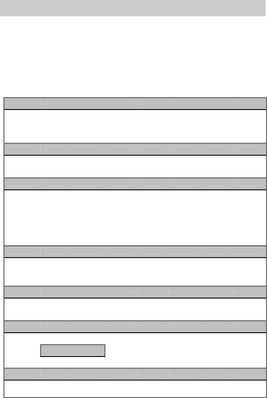
5.6.1. Adjustment of the soft limit
Click on the [Axis] button on the main menu screen to activate the “Soft limit” adjustment function.
Figure 80
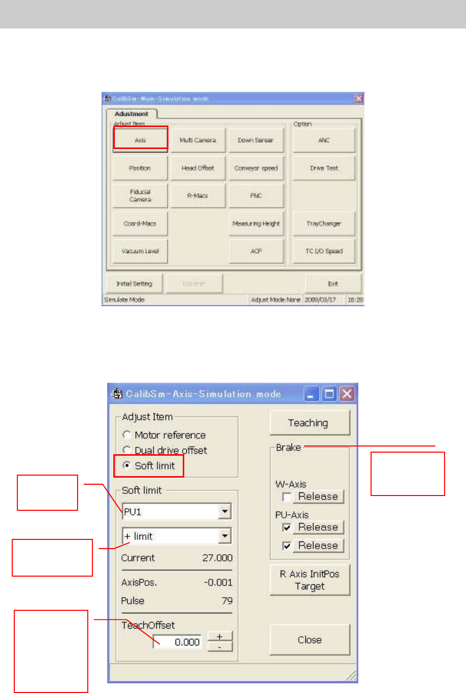
< Main axes (X, Y-axis)>
Normally, the soft limit is set to the position that is shifted by the amount of the offset value inward from
the mechanical limit or the secondary limit.
Figure 81
The function
for releasing
the brake
.
Select
the axis
Select the
axis direction
Input the
offset value
referring to
the offset
values in
Table 2.