YAMAHA-YG系列 换螺杆指导书.pdf - 第14页
Service Engineer Service I nformati on SI080 2008 E-000 = YG series: Replacement proc edure for ball screws of each axis 14/65 2. How to r eplace a ball screw of Y1,2-axis Required tools - Philli ps-head sc rew drive…

Service Engineer
Service Information
SI0802008E-000= YG series: Replacement procedure for ball screws of each axis
13/65
1.4.2. Adjustment after replacing the ball screw
The coordinates of the machine deviate due to the replacement of the parts. Therefore, some works
need to be done in order to restore the coordinates in the simple method.
Caution:
Please make sure to do the necessary work before replacement. Otherwise, you will need to perform
all the adjustment, which requires a great deal of time later on.
<Works to be done>
• Adjust the machien reference.
• Adjust to the reference coordinate after the replacement of the ball screw.
• Check the peak current (With the Servo utility).
* Please refer to the relevant section in “5. Adjustment”.
• Set the ball screw cover. (*Only for the YG88R and YG100R models.)
Set the both side of the pieces of the cover first, then set the center part.
Check if the bolts are tightened properly
1. Press the [Emergency stop] button and check the surrounding area for safety.
2. Check the bolts removed for replacement or loosened are tightened properly.
Check if the bolts are tightened with the appropriate hex wrench and make a mark on the
bolts with the marker pen.
Other items to be checked and done
1. Check if there are any tools used for replacement left in the machine.
2. Check if there are any pieces of cut off cable tie left in the machine.
3. Make sure that all the harnesses are secured properly, and no axes interfere with anything
when they move.
Caution:
Please do not use an air gun for cleaning inside the machine. The blown away dusts may stick to the
moving parts of the axes, which causes the serious problem to the machine.
4. Get ready for the production activity
Put back all the removed parts such as feeders and other supplying equipments to the
original position.
1.5. Necessary adjustment
Note:
Please refer to the relevant section in “YG300 CalibSm Adjustment Manual” for performing the
following adjustment.
• Check and adjust the soft limit of the X-axis
• Check and adjust the coordinate of the ANC nozzle station.
• Check if the ANC consecutive nozzle change works properly after adjusting the coordinate of the
nozzle station.
• Check and adjust the coordinate of the blow station.
* Please use an actual board and perform mounting test.
If the mounting accuracy is not enough, please perform FAMF adjustment.

Service Engineer
Service Information
SI0802008E-000= YG series: Replacement procedure for ball screws of each axis
14/65
2. How to replace a ball screw of Y1,2-axis
Required tools
- Phillips-head screw driver (Standard type)
- Hex wrench set
- Special T-shape hex wrench (Size 5) or ratchet wrench set
- Nipper
- Some cable ties (150mm, 250mm)
- Marker pen (Used after checking if the screws are tightened properly)
- New ball screw for Y1,2-axis (Sub-Assy. Part)
2.1. Work to be done before replacement
The coordinates of the machine deviate due to the replacement of the parts. Therefore, some works
need to be done in order to restore the coordinates in the simple method.
Also, in case the ball screw is broken or the problem such as seizure occurs, the works before the
replacement cannot be performed and various adjustments need to be performed.
Caution:
Please make sure to do the necessary work before replacement. Otherwise, you will need to perform
all the adjustment, which requires a great deal of time later on.
<Works to be done>
- Check the machine reference of each axis
- Set the reference coordinate before replacement of the ball screw.
* Please refer to the relevant section in “5. Adjustment”.
Service Engineer
Service Information
SI0802008E-000= YG series: Replacement procedure for ball screws of each axis
15/65
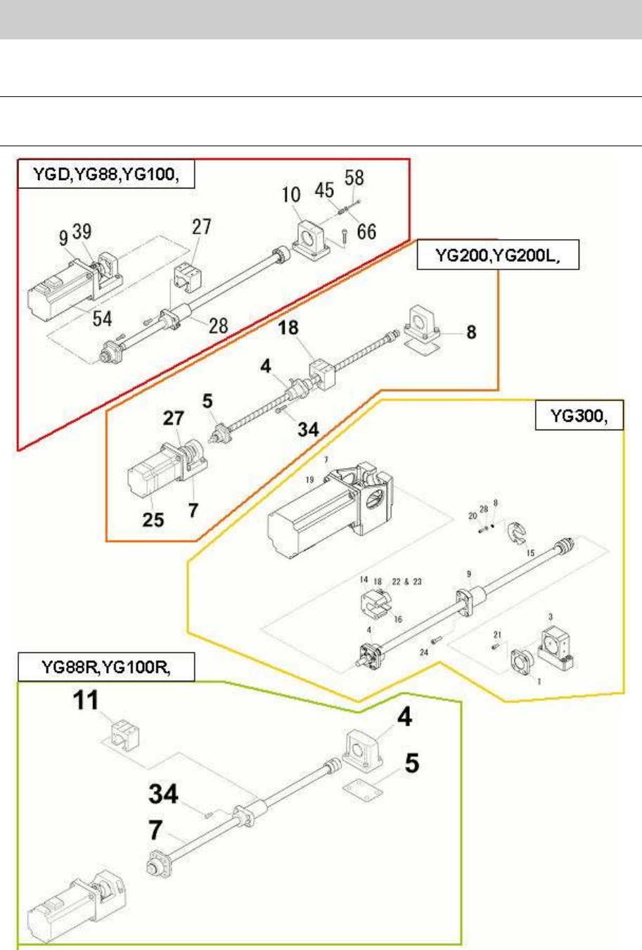
2.2. How to remove the ball screw of Y1,2-axis
Caution:
As some removed parts may contain shims, please be careful not to lose them. Also, please note
down the places where the shims were set.
Figure 16