YAMAHA-YG系列 换螺杆指导书.pdf - 第8页
Service Engineer Service I nformati on SI080 2008 E-000 = YG series: Replacement proc edure for ball screws of each axis 8/65 1.3. How to assembl e the ball screw A ssy . and other attached component s Caution: Stick the…
Service Engineer
Service Information
SI0802008E-000= YG series: Replacement procedure for ball screws of each axis
7/65
* The following procedures are common to all the models.
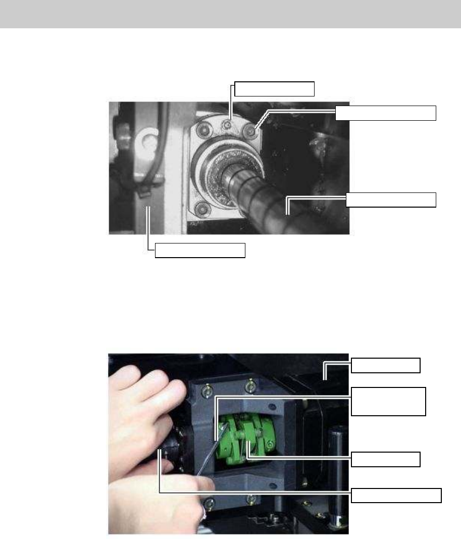
2. Remove the four bolts (M5*16 / BOLT HEX, SOCKET HEAD/ See No.26 in Figure 1) of the screw
nut mounted at the center of the ball screw.
Figure 5
3. Remove the four bolts (M4*14) of the SUPPORT UNIT (See No.20 in Figure 1).
4. Loosen the two bolts at the slotted part (on the screw side) of the coupling (See No.2 in Figure 1).
Figure 6
5. Remove the SUPPOT UNIT (No.20 in Figure 1) from the ball screw, then remove the ball screw
from the X-axis frame.
Grease nipple
Fixing bolts (Qty: 4)
Ball screw of X-axis
HOLDER, HEAD
X-axis motor
Hex wrench
(Size 3)
Coupling
X-axis ball screw
Service Engineer
Service Information
SI0802008E-000= YG series: Replacement procedure for ball screws of each axis
8/65
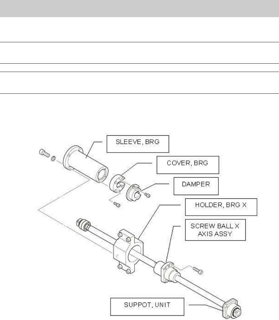
1.3. How to assemble the ball screw Assy. and other attached components
Caution:
Stick the shims to where they were before with the grease. Please be careful not to lose them when
assembling the parts.
Note:
Please make sure to ship the ball screw as a Sub-Assy.
Assemble the parts taking the replaced ball screw Assy. as a model.
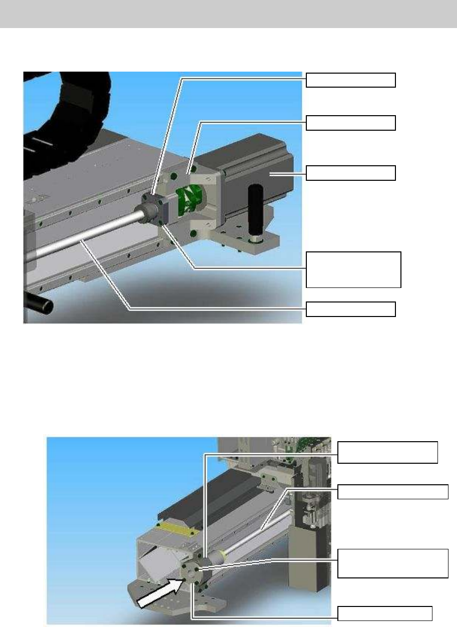
1. Set the Ball screw Assy. to the HOLDER MOTOR X.
After putting the sub-assembled ball screw Assy through the HOLDER HEAD and the HOLDER
BRG X, set the ball screw (on the motor side) in the SUPOPRT UNIT
Figure 7
Service Engineer
Service Information
SI0802008E-000= YG series: Replacement procedure for ball screws of each axis
9/65
2. Set the SUPPORT UNIT in the HOLDER MOTOR (No.3 in Figure 1) and fix it by fully
tightening the four bolts (M4*14).
Figure 8
3. Set the SLEEVE BRG in the HOLDER BRG. X AXIS.
When assembling the parts of YGD, YG88, YG100, YG200(L) and YG300 models.
Insert the SLEEVE BRG into the HOLDER BRG. X AXIS and temporarily secure it with the
four fixing bolts (M5*14).
Figure 9
SUPPORT UNIT
HOLDER, MOTOR
X-AXIS MOTOR
Fixing bolts for the
SUPPORT UNIT
(Qty:4)
X-axis ball screw
HOLDER BRG. X
AXIS
Ball Screw of X-Axis
Fixing blolts(M5*14)
(Qty:4)
SLEEVE BRG