YAMAHA-YG系列 换螺杆指导书.pdf - 第26页
Service Engineer Service I nformati on SI080 2008 E-000 = YG series: Replacement proc edure for ball screws of each axis 26/65 T he layout of the PU-axis for Y G88R and YG 100R Figure 33 KHW-M 9210-000 (Single 440mm) K…
Service Engineer
Service Information
SI0802008E-000= YG series: Replacement procedure for ball screws of each axis
25/65
3. How to replace a ball screw of the PU-axis (Single, Double)
The design of the PU-axis for YG series machines varies depends on the model and the size of the
board.
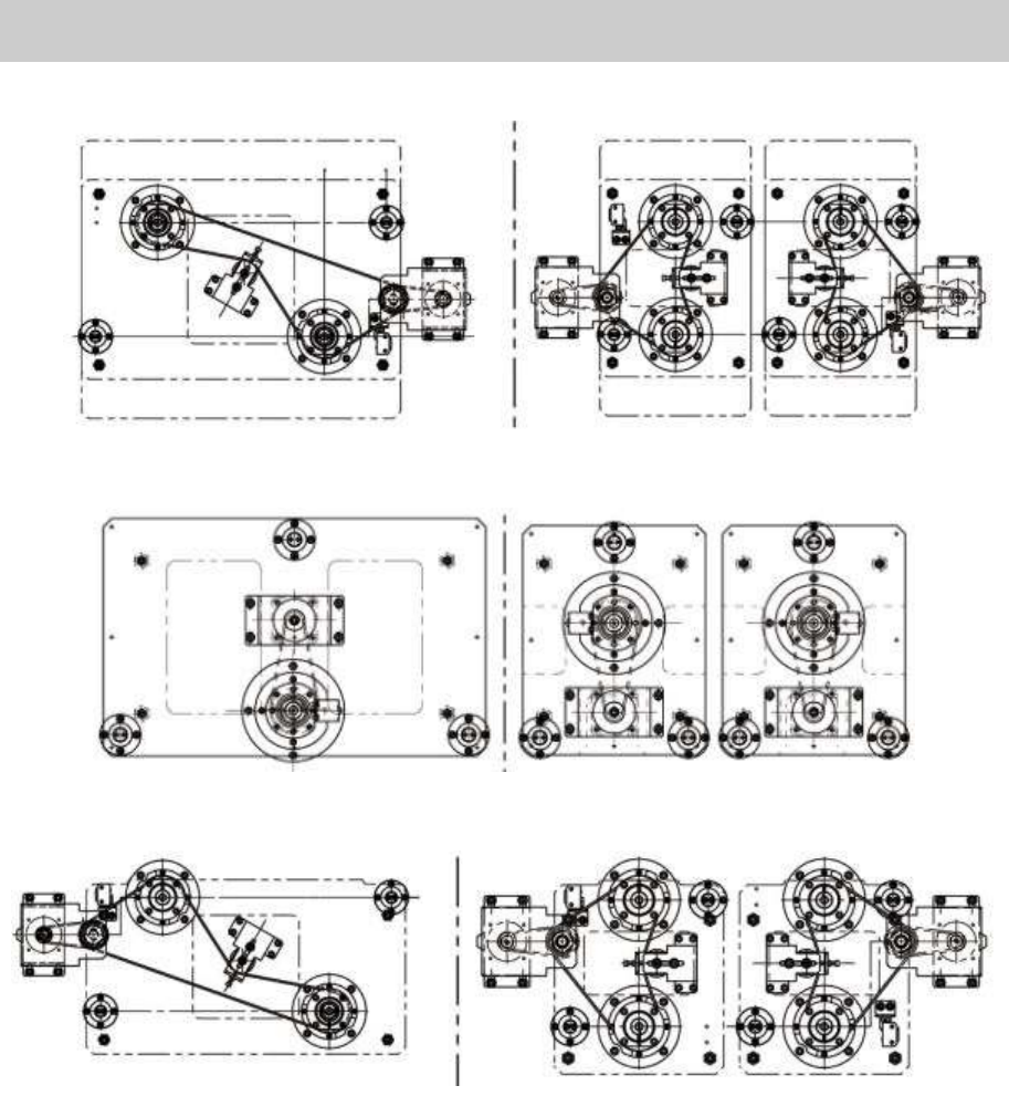
The PU-axis motors of the YG100R (KHV) and YG88R(KHW) are equipped with intermidiate shaft.
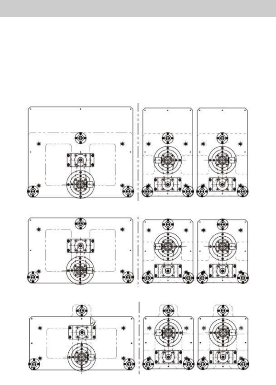
The PU-axis motors of YG100(KGS), YG88(KGR) and YGD(KGM) are direct-drive, and the conveyor
width and the layout of the single and double PU-axis vary as shown in the figure below.
The layout of the PU-axis for YG88 and YG100 models
Figure 32
KGS
-
M9210
-
000 (Single 440mm)
KGS
-
M9210
-
200 (Dou
ble 440mm)
KGS
-
M9210
-
500 (Single 280mm)
KGS
-
M9210
-
400 (Double 280mm)
KGS
-
M9210
-
100 (Single 330mm)
KGS
-
M9210
-
300 (Double 330mm)
Service Engineer
Service Information
SI0802008E-000= YG series: Replacement procedure for ball screws of each axis
26/65
The layout of the PU-axis for YG88R and YG100R
Figure 33
KHW-M9210-000 (Single 440mm)
KHW-M9210-400 (Single 280mm) KHW-M9210-500 (Double 280mm)
KHW-M9210-100 (Single 330mm)
KHW
-
M9210
-
300 (Double 330mm)
KHW-M9210-200 (Double 440mm)
Service Engineer
Service Information
SI0802008E-000= YG series: Replacement procedure for ball screws of each axis
27/65
Required tools
- Hex wrench set
- Phillips-head screw driver (Standard type)
- Nipper
- Tension gauge
- New ball screw for the PU-axis
- Some cable ties
- Marker pen (Used after checking if the screws are tightened properly)
3.1. How to remove the ball screw of the PU-axis
* This section describes how to replace the PU-Axis ball screw taking a single PU-axis of YG88 and
YG100 models as an example.
1. Please make sure to perform Return-to-origin and turn off the machine before replacment.
Caution:
The driving motor of the PU-axis (AC servo) is equipped with a brake, and the brake is applied except
when the motor is rotating. Please do not rotate the shaft with the brake applied.
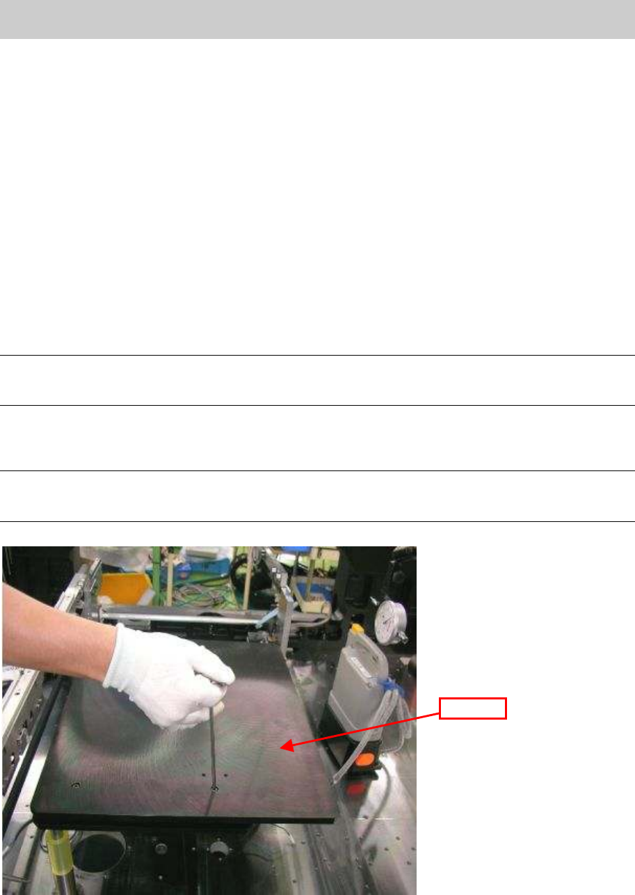
2. Remove the bolts on the upper surface of the push-up that fix the plate 1 with a hex wrench in
order to remove the plate 1.
Caution:
As the plate 1 is heavy, please be careful not to damage the conveyor frame by banging the plate on it
or drop it.
Figure 34
Plate 1