YAMAHA-YG系列 换螺杆指导书.pdf - 第59页
Service Engineer Service I nformati on SI080 2008 E-000 = YG series: Replacement proc edure for ball screws of each axis 59/65 <The drop d own list on the “Sof t limit” screen> By switching the screen, the number o…
Service Engineer
Service Information
SI0802008E-000= YG series: Replacement procedure for ball screws of each axis
58/65
5.7. Adjustment of the soft limit for YG300 model
<Calib Sm Ver.3.02R1.000 or later>
66 axes are used for YG300. This section describes how to adjust the soft limit of each axis.
The adjustment utility named “Soft limit” has been newly added to the “Adjustment utility”, which was
independent from the “Axis” utility.
In the new soft limit adjustment, the coordinate of the mechanical limit is obtained (by teaching), and
then based on the coordinate, the value offset by the amount of the margin is automatically set as the
soft limit value.
The sensors of the axes with secondary limit sensor (X-axis, Y-axis and U-axis) need to be installed
1.0mm inward from the mechanical limit.
Axis name
Margin Limit+ Margin Limit-
X - 2.000 2.000
Y - 2.000 2.000
Z - 0.500 0.500
R - 5.000 5.000
U - 2.000 2.000
W - 1.000 1.000
T - 1.000 1.000
Table 3
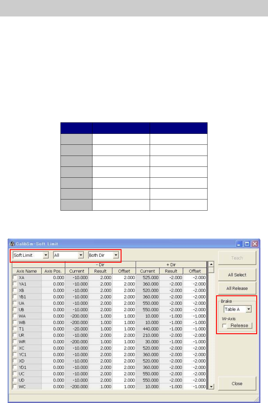
1. Click on the [Soft Limit] button on the Calib Sm main menu to display the “Soft limit” screen.
Figure 82
Service Engineer
Service Information
SI0802008E-000= YG series: Replacement procedure for ball screws of each axis
59/65
<The drop down list on the “Soft limit” screen>
By switching the screen, the number of the axis names in the “Axis Name” column displayed on the
screen can be reduced.
The name of the dropdown list The function
Soft limit Switch the “Soft Limit” screen and the “Init Pos” screen.
All
Switch the “All” screen, the “Table A/B/C/D“ screens and
“Others” screen.
Both Dir
Switch the screen when the adjustment needs to be
performed for both direction (Both Dir), or either - direction
(-Dir) or + direction (+ Dir).
Table 4
2. Press the [Emergency Stop] button and turn off the servo.
Before adjusting the W-axis of the A, B, C, and D table, please make sure to release the “W-axis”
brake.
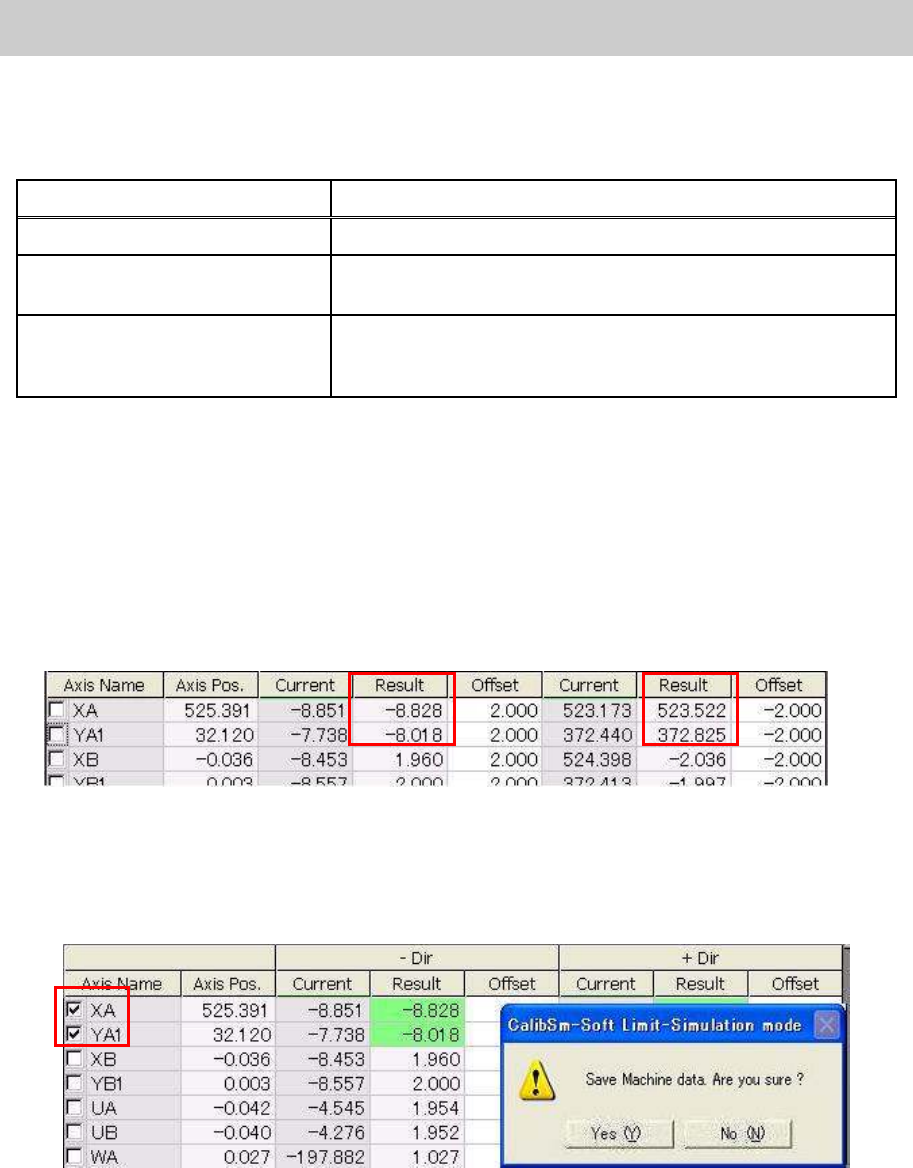
3. Press the axes against the mechanical limit.
Press the axes that need to be adjusted against both the + and – mechanical limit in order to
obtain the “Result” value.
The value obtained by adding the offset value to the maximum value and the minimum value of
the moved range are displayed in the “Result” fields.
Figure 83
4. Tick the boxes of the “Axis Name” column.
Tick the boxes of the axis name adjusted in procedure 3, then click on the [Teach] button.
The fields of the adjusted axes are green highlighted. Check the result and save the data.
Figure 84
5. Check the Soft Limit.
After adjustment, please check if the Soft Limit is set properly by actually moving the axes slowly.
Set the axis speed to lower than 10%, and move the axis from near the soft limit to outward, then
check if the axis stops at the specified position. If it does not, please perform appropriate
adjustment.
Service Engineer
Service Information
SI0802008E-000= YG series: Replacement procedure for ball screws of each axis
60/65
5.8. Check the peak current (with the “Servo” utility)
Note:
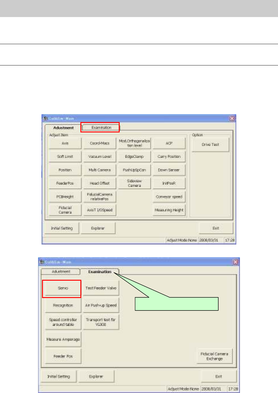
In order to display “Examination” tab of the Calib Sm main menu, you need to login with the login level
higher than “Service”.
1. Select the “Examination” tab on the “Adjustment Utility” and click on the [Servo] button in order to
check the peak current.
<Calib Sm Main menu>
Figure 85
Figure 86
Select the “Examination” tab.