AOI_RS_v85_en.pdf - 第133页
Chap ter3 SPC User Ma nual AOI Repair Station 129 The lower part of the screen shows the componen ts and solders you have selected. T o m odify the conditions for one or more selected components or solders, use the mou…
Chapter3 SPC User Manual
AOI Repair Station
128
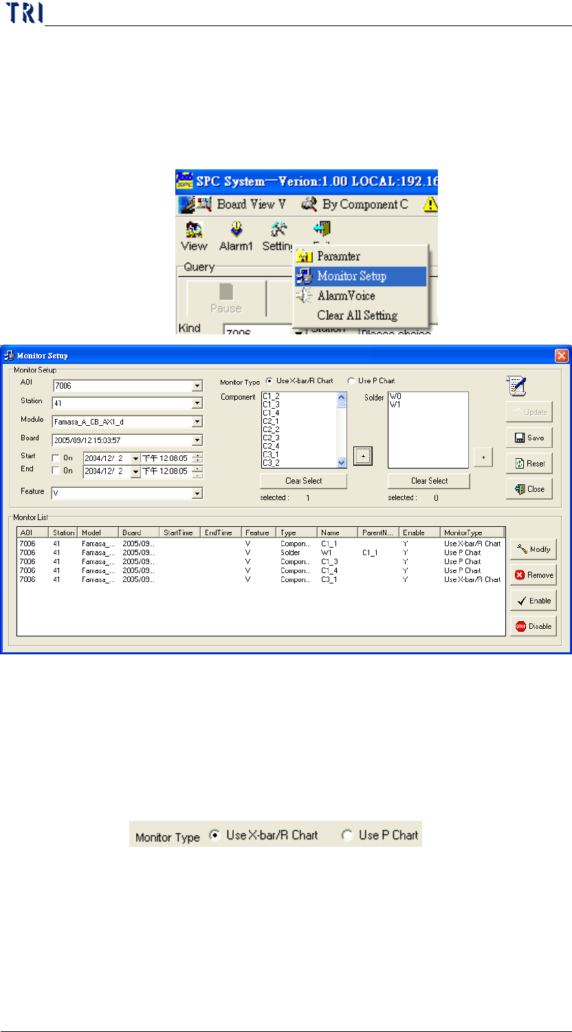
Each time this software starts monitoring, it will monitor the items
you selected in this function in addition to real-time monitoring of
the 12 components and solders in the screen. From the Main
menu, you can click on “
Setting” and then “Monitor Setup” to
display the following screen.
The screen above provides a quick way to find the components and
solders you want to monitor. To select several components or
solders at the same time, press and hold the “
Ctrl” key on your
keyboard and then use the mouse cursor to select the desired
component or solder. After selecting a component or solder,
select an item in “Monitor Type”
( ), then click on the
“+” button on the lower right of the Component or Solder list to
add the selected component or solder into the Monitor List below.
To clear all the items you selected in the Component or Solder list,
just click on the “Clear Select” button below the list and all items
will be cleared.
Chapter3 SPC User Manual
AOI Repair Station
129
The lower part of the screen shows the components and solders you
have selected. To modify the conditions for one or more selected
components or solders, use the mouse cursor to select the items for
to be modified and then click on the “
Modify” button on the lower
right. At this time, the system will display the detailed settings of
this item in the middle of the upper part of the screen. After
modifying, click on the “Update” button on the lower right to
complete updating this item. To delete one or more selected items,
select the item (to select several items at the same time, press and
hold the “Ctrl” key on your keyboard and then use the mouse
cursor to select the desired components or solders) and then click
on the Delete button on the lower right. In addition, you can
disable or enable one or more items just by clicking on the Disable
or Enable button on the lower right. Once an item is disabled, the
system will not include it in the monitor list. To resume
monitoring an item, just enable it again.
When all settings are completed, remember to click on the “Save”
button so that the system will save all these changes. To reset the
settings, just click on the “Reset” button and then click on the
“Close” button.
7.4.1.8
Alarm Setting
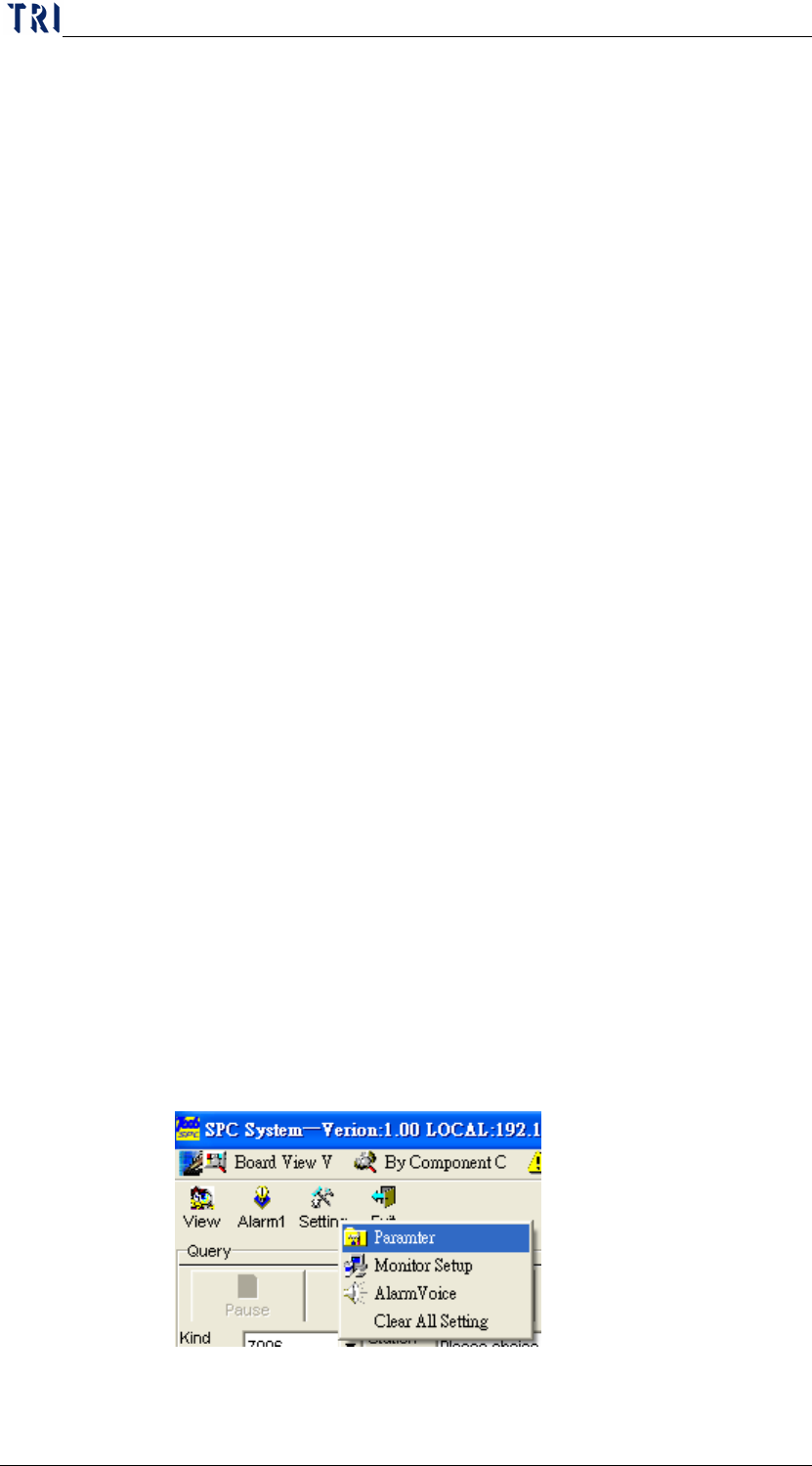
This is for setting the alarm (error) conditions. That is, when the
data in the control chart reaches the scenario in the alarm condition,
this indicates that errors has occurred in the component or solder
process in the current control chart. From the Main menu, you
can click on “
Setting” and then “Parameter” to display the
following screen.
The alarm setting will be separated to X bar-R Chart and P Chart.
They are explained below.
Chapter3 SPC User Manual
AOI Repair Station
130
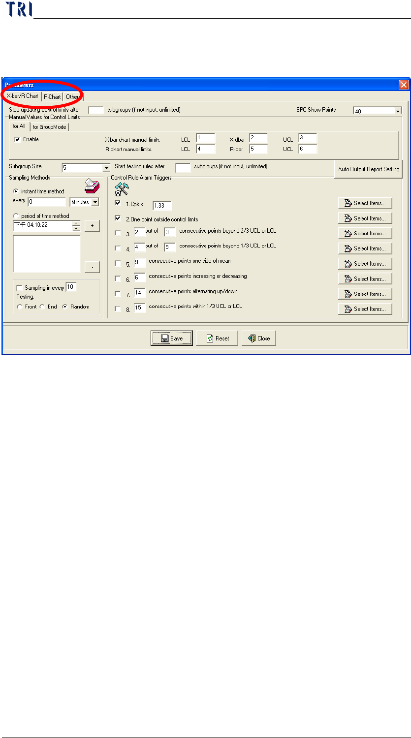
X bar-R Chart: Change to page [X-bar/R Chart] to set
parameters.
The “Control Rule Alarm Triggers” area is for setting
the alarm parameters. Check (
√) the check box before
each item if you want to enable this said item. The
description of each item is as follows:
If the Cpk value computed after each sampling is
smaller than the value set in this item, this
indicates that an error has occurred.
If the X mean value or the R value computed after
each sampling is greater than the control upper or
lower limit computed at that time, this indicates
that an error has occurred.
If consecutive points in the control chart exceed
2/3 of the control upper or lower limit, this
indicates that an error has occurred.
If consecutive points in the control chart exceed
1/3 of the control upper or lower limit, this
indicates that an error has occurred.
If consecutive points in the control chart exist on
one side of the control mean value, this indicates
that an error has occurred.