AOI_RS_v85_en.pdf - 第144页
Chap ter3 SPC User Ma nual AOI Repair Station 140 display all error information and open a “Commen t” field to input user remarks as described below: When error point occurs in the control chart, click on it to display t…
Chapter3 SPC User Manual
AOI Repair Station
139
system will generate warning beeps when an error occurs. The
“Save to Default” option indicates whether or not to save the
“always on top”, “always shows” and “vocalize alarm sound”
settings as the default values so that the system will use these
settings the next time you start this software.
The “Alarm Message” block below the task bar displays the
information concerning an alarm message and the description of each
item is as follows:
GUID: Message no. The system automatically assigns a unique
ID number for each alarm message.
Time: Time the message occurs.
Name: Name of component or solder where the message occurs.
Filter: The conditions for query the component.
Machine is the type of machine, 7006 (SPI), 7100 (AOI) or
ICT.
Station means the machine ID.
Feature means the selected feature, it may be V (Volume), A
(Area), H (Height), PX (X shift) or PY (Y shift) for 7006
(SPI); it may be X (X shift), Y (Y shift) or Theta (rotating
angle) for 7100 (AOI) and may be Measure for ICT.
Reason: Reason for the occurrence of this message. You can
find out the type of error through this information.
Data: Sample value that causes this message to occur.
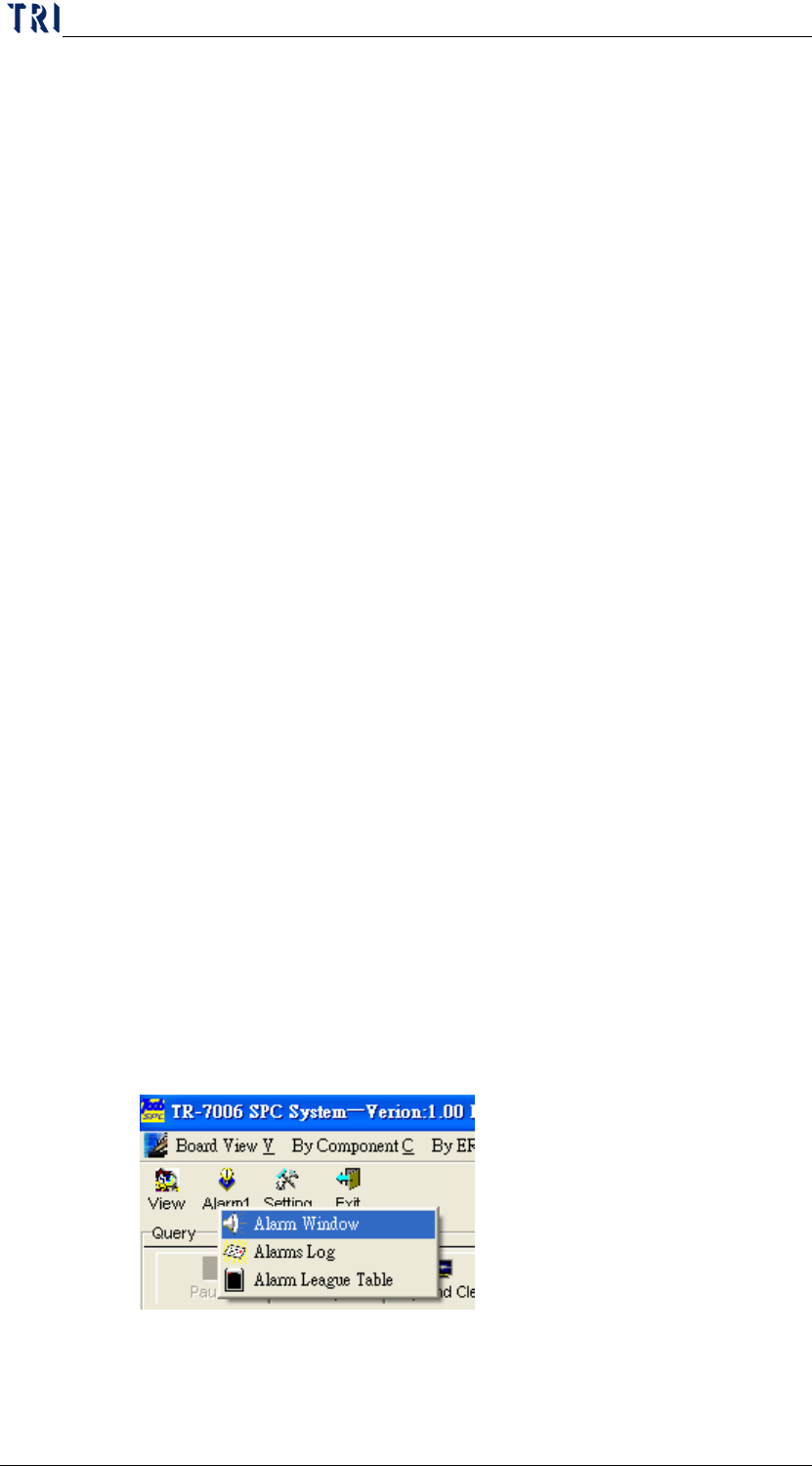
Aside from the system opening this Alarm Window automatically
whenever an error occurs, you can also open the Alarm Window by
clicking on “
Alarm” and then “Alarm Window” in the Main menu as
shown below.
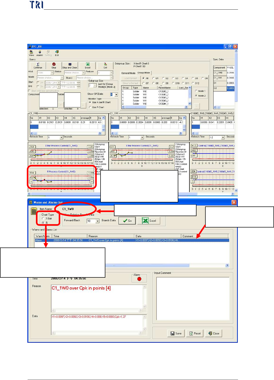
You can click on any control chart during or after monitoring to
Chapter3 SPC User Manual
AOI Repair Station
140
display all error information and open a “Comment” field to input user
remarks as described below:
When error point occurs in
the control chart, click on it
to display the screen below.
Current display chart types. Click on
chart type you want to view:
X
-
bar: X
-
bar chart; R: R Chart
Name of control chart monitor item
Display all error information
for this control chart
Chapter3 SPC User Manual
AOI Repair Station
141
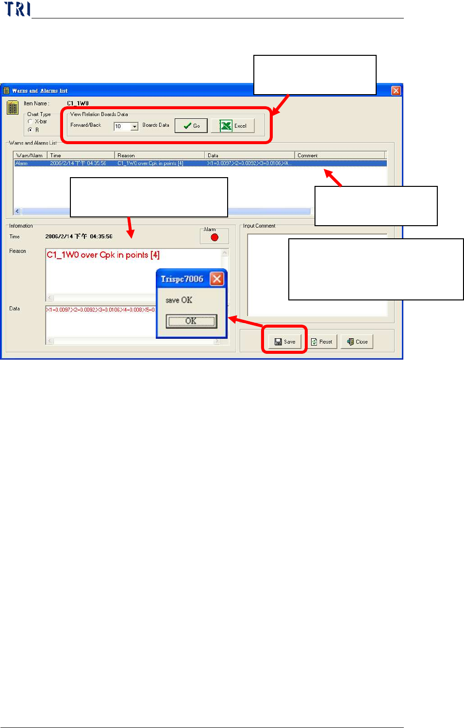
Besides, user can use [View Relation Boards Data] to display the data
of former and the later few boards of the abnormal data. User sets the
number of boards he wants to review then press [Go] to show the other
window to review the data of relating boards, as the window shown
below. Or user can press [Excel] to output excel file directly.
Click on the abnormal
data to review.
Display detailed information
of alarm you selected.
You can key in the remarks for this
alarm data for future tracking. Click
on Save after keying in.
Click on the alarm data you
want to view