Nordson_EFD_GV_Series_Operating_Manual.pdf - 第141页
GV Series Automated Dispensing Systems 141 www.nordsonefd.com info@nordsonefd.com +1-401-431-7000 Sales and service of Nordson EFD dispensing systems are available worldwide. # Click Step Reference Image 7 2 > • Enter…
GV Series Automated Dispensing Systems
140 www.nordsonefd.com info@nordsonefd.com +1-401-431-7000 Sales and service of Nordson EFD dispensing systems are available worldwide.
Appendix E, Multi-Needle Setup and Use (continued)
To Use the Multi Needle Command in a Program
PREREQUISITES
The system is properly set up. Refer to “Setting Up and Calibrating the System (Required)” on page48.
The additional dispensers are installed and set up and the Multi Needle capability is enabled. Refer to “To Enable
Multi-Needles Dispensing” on page137 and to “To Set the Camera-to-Tip Offsets for Multiple Dispensers” on
page137.
A test workpiece is positioned on the fixture plate or work surface.
NOTE: This procedure explains the programming process for two dispensers. Repeat steps as needed to add
commands for additional dispensers (up to four dispensers can be installed).
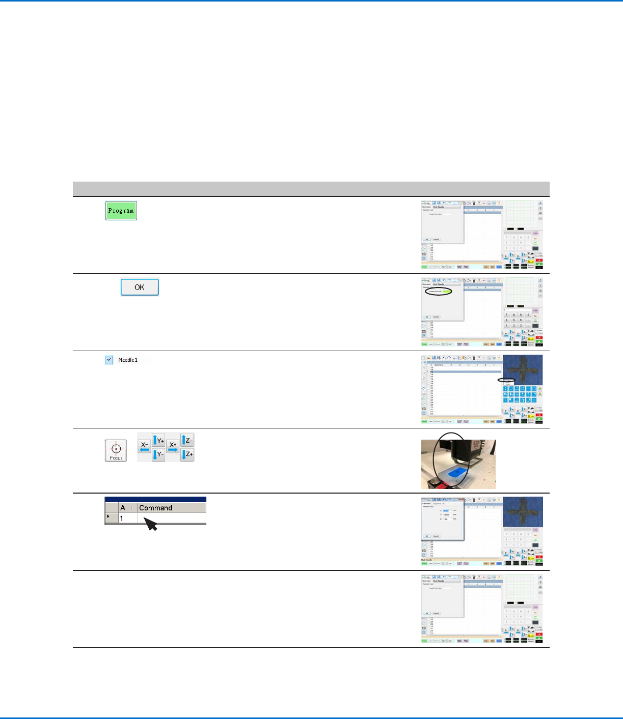
# Click Step Reference Image
1
> MULTI NEEDLE
• Click the PROGRAM tab
• Double-click the address row where you
want to insert a Multi Needle command and
select MULTI NEEDLE.
2
1 >
• Enter the number of the dispenser to
dispense from at this point in the program (in
this example, Dispenser 1).
• Click OK to save.
3
• In the Secondary View screen, right click and
check the NEEDLE 1 checkbox.
4
>
• Click the FOCUS icon to focus the camera.
• Jog the camera until the camera crosshairs
are centered over the desired target on the
workpiece.
5
• Insert the required commands for
Dispenser1 (for example, create dispense
dots or lines).
6
MULTI NEEDLE
• Double-click the address row where you
want to insert the second Multi Needle
command and select MULTI NEEDLE.
Continued on next page
GV Series Automated Dispensing Systems
141www.nordsonefd.com info@nordsonefd.com +1-401-431-7000 Sales and service of Nordson EFD dispensing systems are available worldwide.
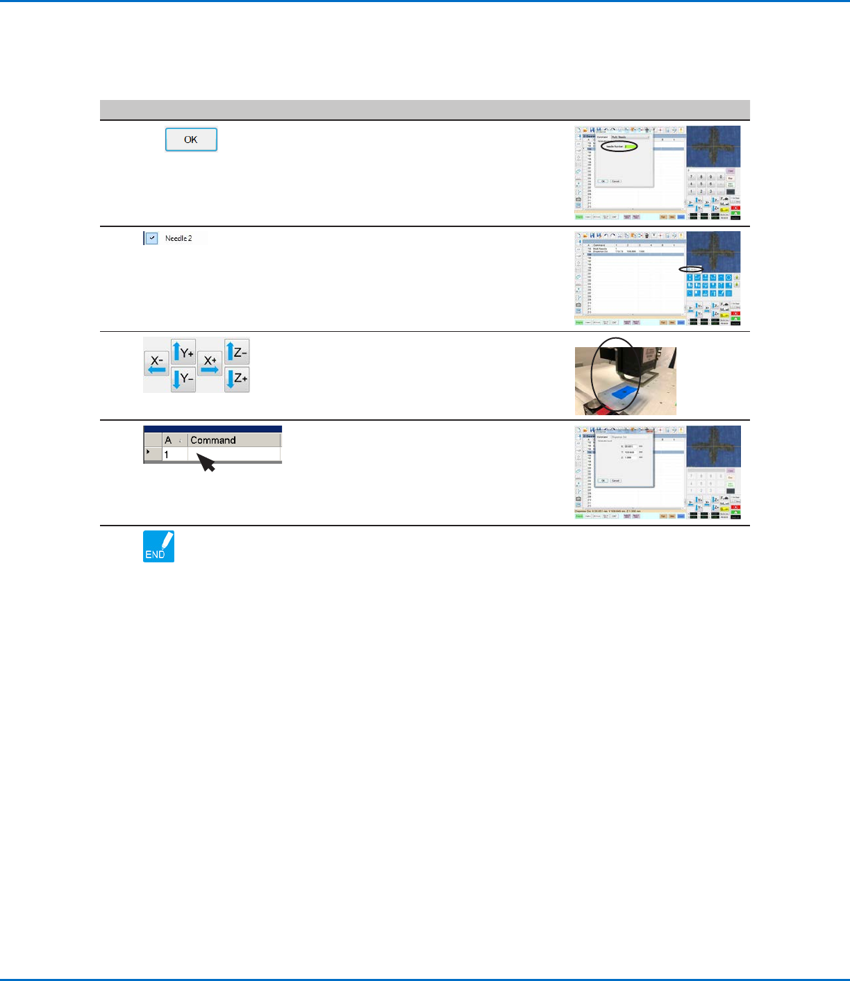
# Click Step Reference Image
7
2 >
• Enter the number of the dispenser to
dispense from at this point in the program (in
this example, Dispenser 2).
• Click OK to save.
8
• In the Secondary View screen, right click and
check the NEEDLE 2 checkbox.
9
• Click the FOCUS icon to focus the camera.
• Jog the camera until the camera crosshairs
are centered over the desired target on the
workpiece.
10
• Insert the required commands for
Dispenser2 (for example, create arc or fills).
11
• Click END PROGRAM to end the program.
The system will dispense from Dispenser 1
or Dispenser 2 as programmed.
Appendix E, Multi-Needle Setup and Use (continued)
To Use the Multi Needle Command in a Program (continued)
GV Series Automated Dispensing Systems
142 www.nordsonefd.com info@nordsonefd.com +1-401-431-7000 Sales and service of Nordson EFD dispensing systems are available worldwide.
To Set Up the Height Sensor
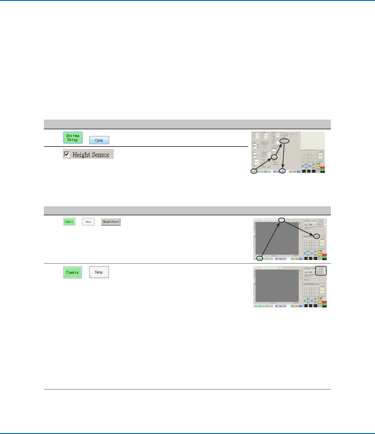
# Click Step Reference Image
1
> >
• Click the CAMERA tab, click SETUP at the
top of the Camera screen, and then click the
HEIGHT SENSOR tab.
The Height Sensor fields appear.
2
>
• In the fields located at the top right corner of
the Height Sensor area, enter the following
values:
- Probe Output: As connected on your
system (default = 8)
- Sensor Input: As connected on your
system (default = 8)
- Detect Speed (mm/s): 5 (range = 1–20)
- Travel Limit (mm): 20 (range = 1–100)
NOTES:
• Detect Speed is how fast the Zaxis lowers
towards the workpiece after the height
sensor probe extends.
• Travel Limit is the range within which the
Zaxis moves to detect the Z-height value.
Continued on next page
AppendixF, Height Sensor Setup and Use
The optional height sensor can detect any variation from the original Z height program values from workpiece
to workpiece. If the Z height changes, the system detects the new Z height values and adjusts the program
accordingly.
PREREQUISITES
The height sensor is installed and the cable is connected to the I/O port. Refer to the instructions provided with
the height sensor.
The system is properly set up. Refer to “Setting Up and Calibrating the System (Required)” on page48.
A test workpiece is positioned on the fixture plate or work surface.
To Enable the Height Sensor
#
Click Step Reference Image
1
>
• Click the SYSTEM SETUP tab, then click
OPEN.
2
• Check HEIGHT SENSOR.
When the height sensor is enabled, the
Toggle Probe button appears in the tab bar.