Nordson_EFD_GV_Series_Operating_Manual.pdf - 第21页
GV Series Automated Dispensing Systems 21 www.nordsonefd.com info@nordsonefd.com +1-401-431-7000 Sales and service of Nordson EFD dispensing systems are available worldwide. Position the Robot and Install and Connect Com…
GV Series Automated Dispensing Systems
20 www.nordsonefd.com info@nordsonefd.com +1-401-431-7000 Sales and service of Nordson EFD dispensing systems are available worldwide.
Position the Robot and Install and Connect Components
Refer to the Quick Start Guide and to this section as needed to install the system components and make
connections.
NOTES:
• The components of an automated dispensing system vary. Steps for a complete system with all available
components are provided in this manual and in the Quick Start Guide. Perform only the steps that apply to your
system.
• If the system is being used in the European Community, the robot is shipped with an enclosure or light curtain
that (1) prevents an operator from entering the robot’s work area and (2) generates an emergency stop signal if the
enclosure door switch is opened while the robot is running.
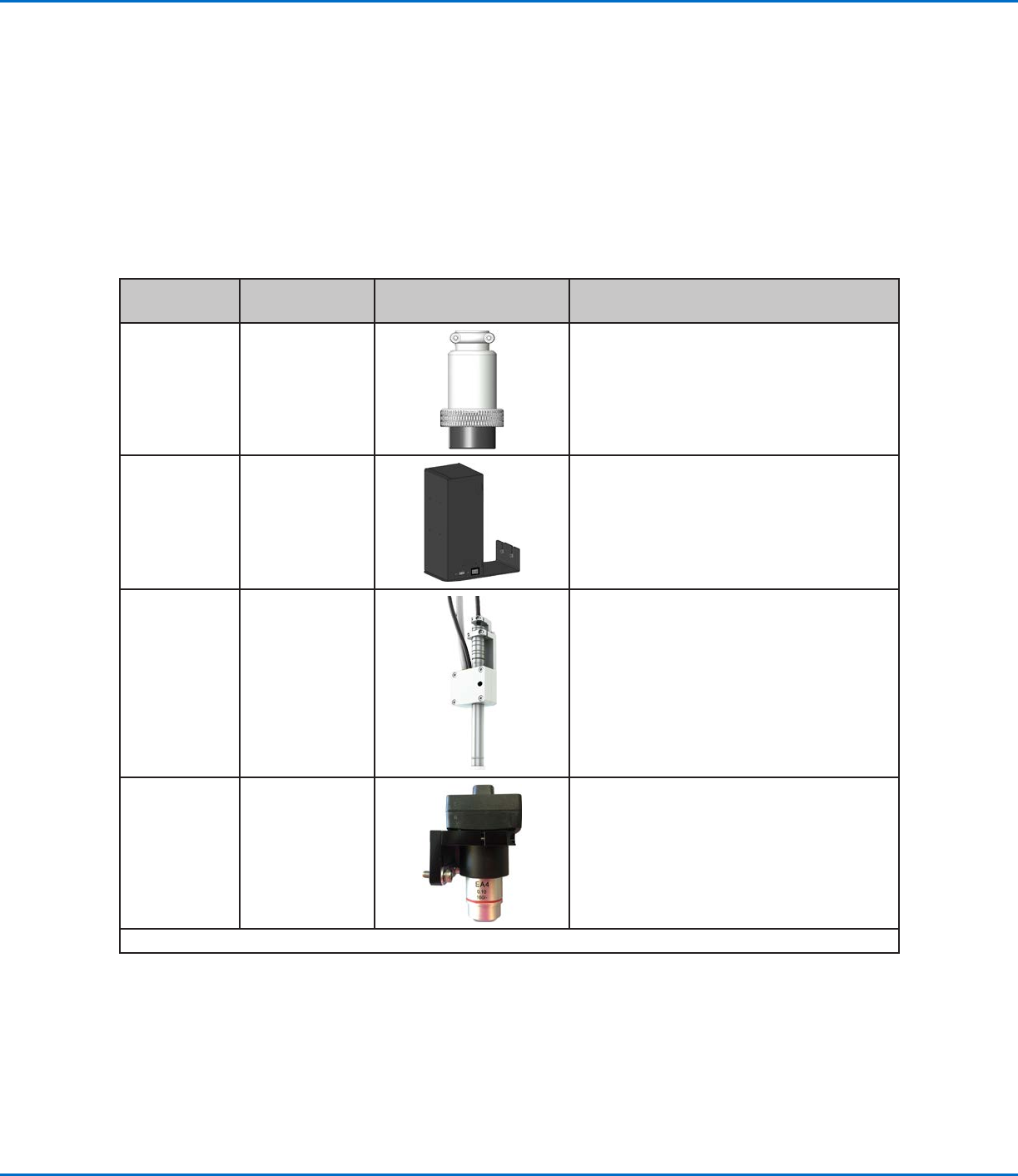
Applicability Item
Components to Install
or Connect
Installation Tasks
All models Input / output
safety plug
(SHORTED)
Connect the 2-pin input / output safety
plug to the 2-pin port on the start / stop
box.
All models DispenseMotion
controller
Mount the DispenseMotion controller on
the shelf.
Install the shelf-and-controller assembly on
the left upright bracket.
Make the connections shown on the Quick
Start Guide.
G4V Pencil camera
Install the bracket.
Install the camera.
Route the camera cable through the
dragon chain on the Z axis.
Secure the cable by using the provided
cable clips to attach it to the Zaxis.
Connect the cable to USB-CCD on the
DispenseMotion controller.
G8V CCD camera
Install the camera and bracket assembly.
Connect the camera cable to the camera.
Route the camera cable through the
dragon chain on the Z axis.
Connect the cable to USB-CCD on the
DispenseMotion controller.
Continued on next page
GV Series Automated Dispensing Systems
21www.nordsonefd.com info@nordsonefd.com +1-401-431-7000 Sales and service of Nordson EFD dispensing systems are available worldwide.
Position the Robot and Install and Connect Components (continued)
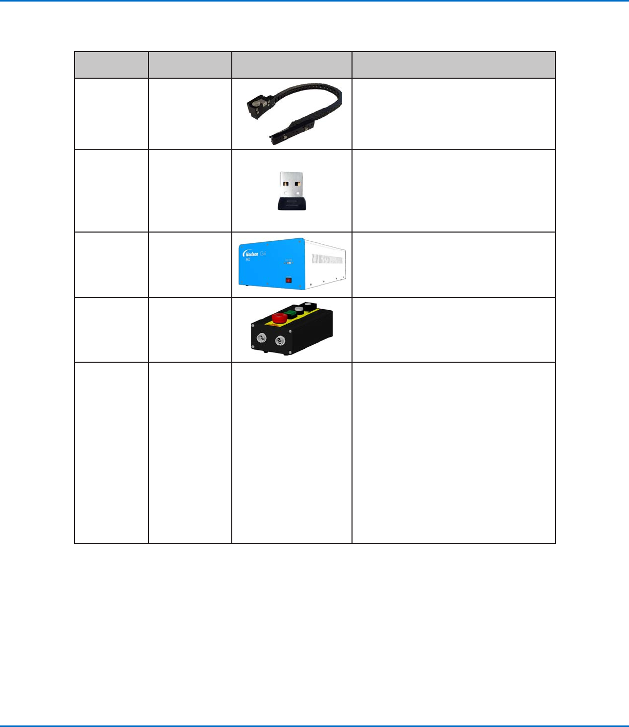
Applicability Item
Components to Install
or Connect
Installation Tasks
All models Tip detector
(optional)
Install the tip detector.
Connect the cable to the Tactile port on the
back of the robot.
All models Monitor,
keyboard, and
mouse (not
shown); dongle
for wireless
keyboard and
mouse
Connect the monitor.
Connect the wireless keyboard and mouse
dongle to USB 4 on the DispenseMotion
controller.
All models GV operation box Position the GV operation box such that
(1) cables can be easily connected and
(2)operators can access the front panel.
Make the connections shown on the Quick
Start Guide.
All models Start / stop box
Position the start / stop box such that
(1)cables can be easily connected and
(2)operators can access the controls.
Make the connections shown on the Quick
Start Guide.
All models Dispenser
components
As applicable
Mount the syringe barrel or dispensing
valve holder (as applicable) on the Zaxis;
choose mounting holes that allow a
maximum workpiece clearance but also
allow the dispensing tip to reach all areas
on the workpiece where dispensing is
required.
To prevent damage to the camera,
make sure the dispensing tip position is
lower than bottom of the camera. Refer
to “Check the Camera and Dispenser
Installation” on page22.
Refer to the dispensing equipment manuals
for all other dispensing system installation
steps.
GV Series Automated Dispensing Systems
22 www.nordsonefd.com info@nordsonefd.com +1-401-431-7000 Sales and service of Nordson EFD dispensing systems are available worldwide.
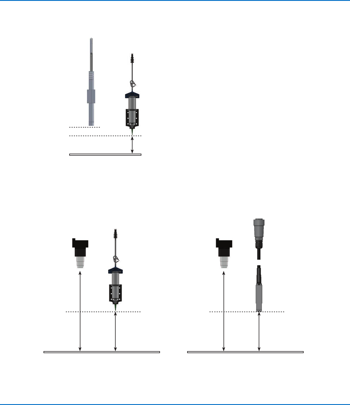
Check the Camera and Dispenser Installation
To prevent damage to the camera, make sure the dispensing tip position is lower than bottom of the camera.
Example of correct pencil camera installation (dispensing tip lower than the bottom of the camera)
Tip bottom
Camera bottom
Work surface
Example of correct CCD camera installation (dispensing tip
lower than the bottom of the camera)
Example of correct CCD camera installation (higher than the
bottom of the tip) for a PICO
®
valve installation
Camera
focal
distance
Tip distance
from robot
work surface
(lower than
camera)
Tip bottom
Camera
focal
distance
Tip distance
from robot
work surface
(lower than
camera)
Tip bottom