Nordson_EFD_GV_Series_Operating_Manual.pdf - 第39页
GV Series Automated Dispensing Systems 39 www.nordsonefd.com info@nordsonefd.com +1-401-431-7000 Sales and service of Nordson EFD dispensing systems are available worldwide. System Setup Scr een Click the System Setup ta…
GV Series Automated Dispensing Systems
38 www.nordsonefd.com info@nordsonefd.com +1-401-431-7000 Sales and service of Nordson EFD dispensing systems are available worldwide.
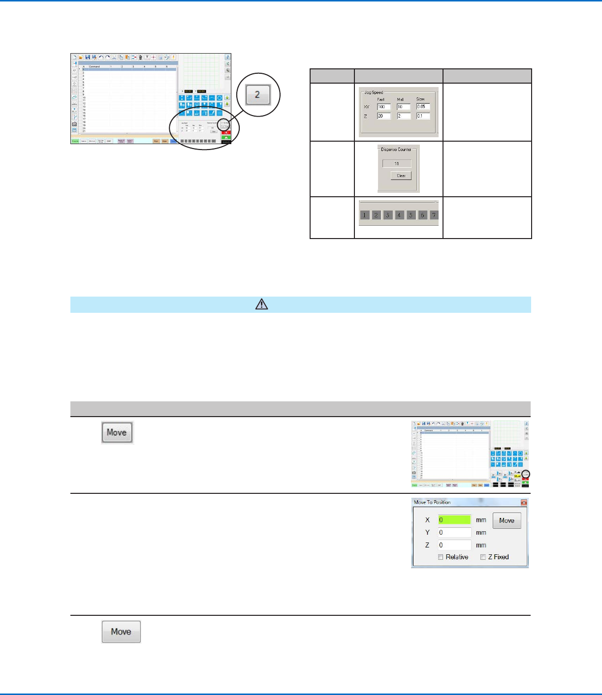
View 2
Field Screen Area Function
Jog
Speed
Allows you to change
the jog speed settings
by entering values
using the keyboard.
Dispense
Counter
Shows how many
dispense actuations
have occurred. Click
CLEAR to reset the
counter to zero (0).
Input /
output
triggers
Allows you to trigger
a connected input /
output by clicking the
input / output number.
Navigation and Jogging Window (continued)
View 2 of the navigation and jogging window
CAUTION
Risk of equipment damage. When moving the tip to a specific location, do not exceed the axis limits (specified
under System Setup > Axis Limits), especially for the Z axis. Doing so can damage the robot or cause the tip to
collide with the substrate.
How to Move the Tip to a Specific Location
You can use the Move button in the jog window to move the tip to a specific set of coordinates.
#
Click Step Reference Image
1
• In the jog window, click MOVE.
The Move to Position window opens.
2 • Enter the desired coordinates. As applicable,
select or deselect the following checkboxes:
- Relative: If selected, the tip will move to the
entered coordinates relative to its current
location. If deselected, the tip will move
to the entered coordinates based on the
home position (0, 0, 0).
- Z Fixed: When selected, locks out the Z
axis so only X and Y coordinates can be
entered.
3 • Click MOVE.
The tip moves to the specified location.
• Close the window.
GV Series Automated Dispensing Systems
39www.nordsonefd.com info@nordsonefd.com +1-401-431-7000 Sales and service of Nordson EFD dispensing systems are available worldwide.
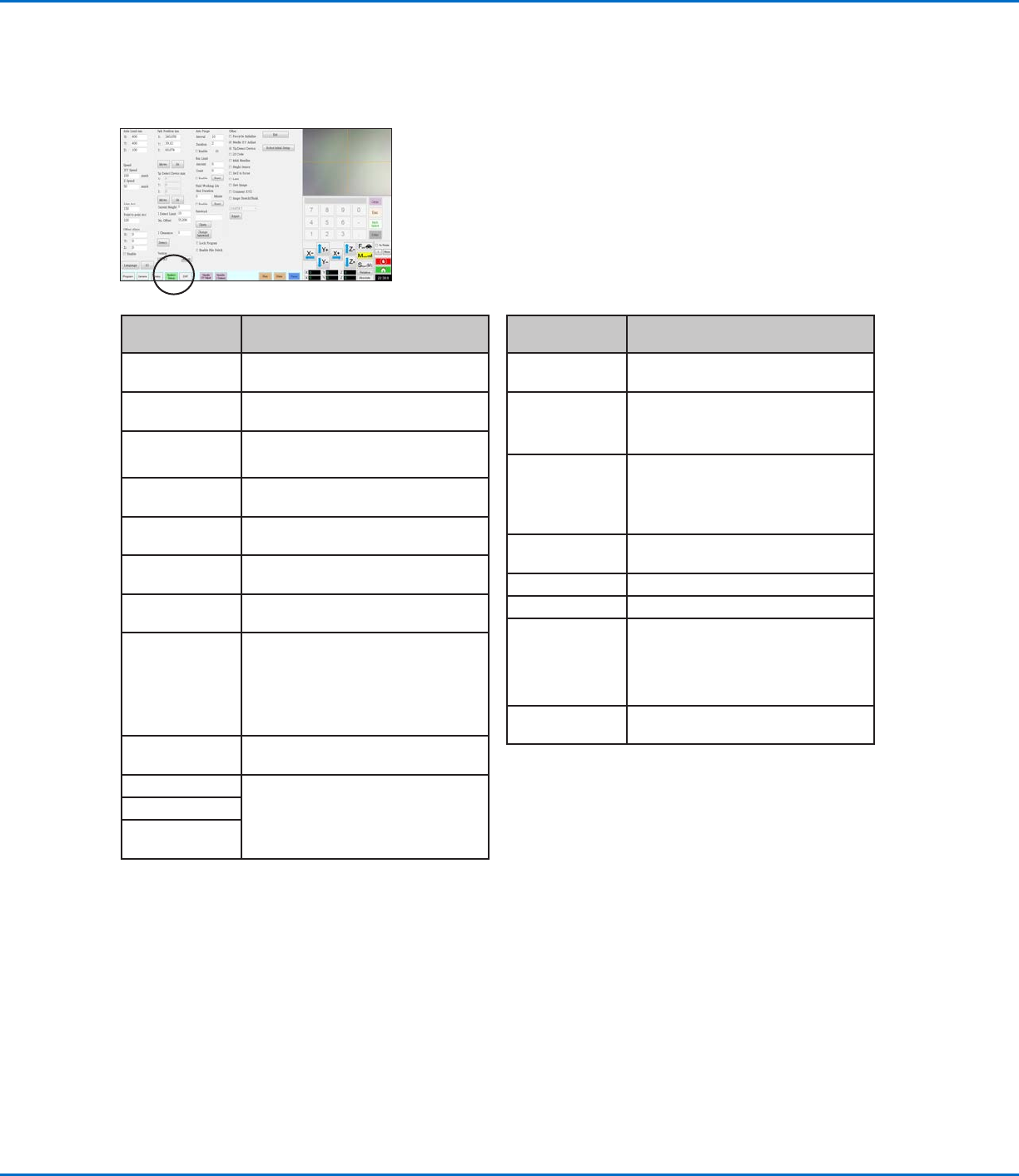
System Setup Screen
Click the System Setup tab to go to the System Setup screen. This screen includes fields for system settings and
provides access to the Robot Initial Setup wizard. Refer to the sections of the manual referenced below for detailed
information on these fields.
System Setup
Screen Area
Function
Axis Limit Refer to “Setting System Parameters”
on page44.
Speed Refer to “Setting System Parameters”
on page44.
Line Acc
Point to point Acc
Refer to “Setting System Parameters”
on page44.
Offset Alarm Refer to “Setting System Parameters”
on page44.
Language Refer to “Setting System Parameters”
on page44.
IO Refer to “Setting Up Inputs / Outputs”
on page58.
Park Position Refer to “Setting System Parameters”
on page44.
Tip Detect Device Used only as needed for manual
calibration of the tip-to-workpiece
offset in place of using the Robot Initial
Setup wizard. Refer to “AppendixB,
Non-Wizard Setup Procedures” on
page 124.
Version Shows the current version of the
software
Auto Purge Refer to “How to Set Up Auto Purge,
Program Cycle Limits, or Fluid Working
Life Limits” on page82.
Run Limit
Fluid Working
Life
System Setup
Screen Area
Function
Password Refer to “Setting Password Protection”
on page47.
Lock Program
Enable File
Switch
Refer to “How to Lock or Unlock a
Program” on page65.
Other Allows you to enable or disable a
variety of system-level settings.
Refer to “Other” on page46 for
details.
Model drop-
down menu
Specifies the robot model.
Expert For advanced users only.
Exit Closes the software.
Robot Initial
Setup
Opens the system setup and
calibration wizard. Refer to “Setting Up
and Calibrating the System (Required)”
on page48 for the system setup
procedures.
Light (If present) Refer to “Setting System Parameters”
on page44.
GV Series Automated Dispensing Systems
40 www.nordsonefd.com info@nordsonefd.com +1-401-431-7000 Sales and service of Nordson EFD dispensing systems are available worldwide.
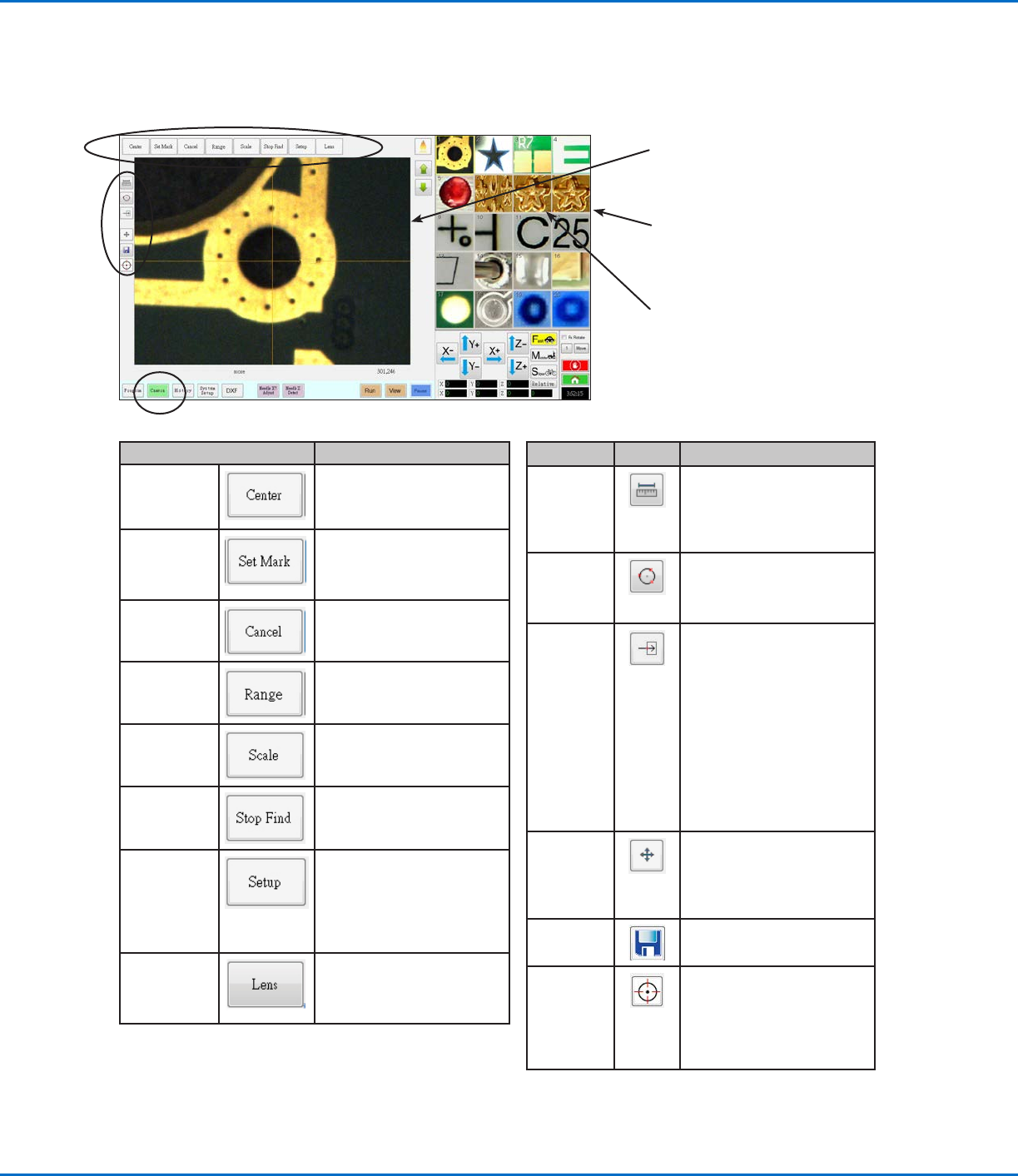
Camera Screen, Tab Bar, and Icons
Click the CAMERA tab to go to the Camera screen. The actual view of what the camera sees appears in the Primary
View screen and the Mark Library appears in the Secondary View screen. The tabs at the top of the Camera screen
are used for camera setup and mark creation.
Camera Screen Tab Function
Center
Moves the camera focal point
to the center of an object
Set Mark
Sets a mark. Refer to “About
Marks” on page28 and to
“How to Create a Mark” on
page70.
Cancel
Cancels the last camera-
related action
Range
Sets the area within which the
system searches for a mark
Scale
Scales the screen to match
the camera view scale (occurs
during setup)
Stop Find
Stops the attempt to find a
mark
Setup
Opens the Camera Setup
window that provides access
to important setup fields
related to the camera. Refer
to “Camera Setup Screen” on
page43.
Lens Opens the Camera Properties
window. Refer to “Camera
Properties Window” on
page41 for details.
Icon Name Icon Function
Measure
Length
Measures the distance
between two points. Refer
to “How to Measure a Path
or Circle on a Workpiece” on
page65.
Measure
Circle
Diameter
Measures the diameter of
a circle. Refer to “How to
Measure a Path or Circle on a
Workpiece” on page65.
Arrow
Accesses advanced
functionality for deposit
verification using the optional
OptiSure
™
add-on software.
This icon is enabled only
when the OptiSure add-on is
unlocked.
Refer to “OptiSure Software
Key” on page91 for the
OptiSure kit part number.
Refer to the OptiSure manual
for operating instructions.
Touch Move
When toggled, moves the
camera to the point clicked
and moves the focal point
to the center of the viewing
screen
Save
Saves the displayed camera
image as a bitmap (*.bmp) file
CCD Focus
Automatically moves the
Zaxis to the focus position
established during Robot
Initial Setup (Step 5 or 6),
or as defined in the camera
setup window (under Offset)
Primary View screen shows the actual
camera view when the Camera tab is
selected
Secondary View screen shows the Mark
Library when the Camera tab is selected
Right-click on any image and then select
PROPERTY to open the Template Match
window. Refer to “Template Match
and Area Windows” on page42 for
information about this window.