Nordson_EFD_GV_Series_Operating_Manual.pdf - 第75页
GV Series Automated Dispensing Systems 75 www.nordsonefd.com info@nordsonefd.com +1-401-431-7000 Sales and service of Nordson EFD dispensing systems are available worldwide. How to Use Marks to Dispense onto a Plain W or…
GV Series Automated Dispensing Systems
74 www.nordsonefd.com info@nordsonefd.com +1-401-431-7000 Sales and service of Nordson EFD dispensing systems are available worldwide.
How to Use Marks to Dispense onto a Plain Workpiece (continued)
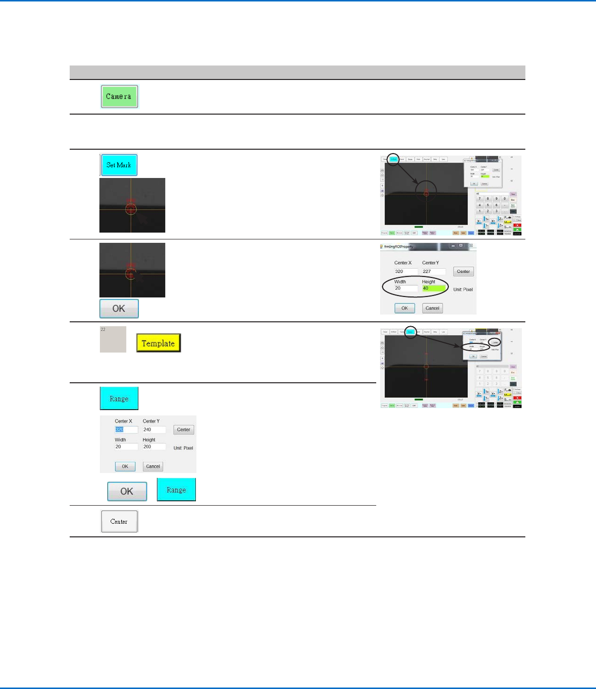
To Create Horizontal and Vertical Marks on a Plain Workpiece
# Click Step Reference Image
1
• Click CAMERA to go to the camera
screen.
2
• Bring the image into focus. Refer to
“Camera” on page18 as needed for
instructions on focusing the camera.
3
>
• Click SET MARK, then click and drag a
red rectangle over the first horizontal
target on the workpiece.
• Center the red rectangle on the edge of
the workpiece by clicking and dragging
a corner.
4
>
• Double-click the crosshairs in the center
of the red rectangle and then enter the
desired values for Width and Height (20
and 40 in this example).
• Click OK to save the values.
5
>
• Click a socket in the Mark Library to
save the mark, then click TEMPLATE
when the Template Match window
appears.
• Make a note of the Mark No.
6
>
> >
• Click RANGE to set where the system
searches for the mark.
• Double-click in the center of the mark
and enter Width and Height values.
NOTE: For horizontal marks, the Width
value must be the same as the Width
specified previously (20 in this example).
• Click OK.
• Click RANGE again to save.
7
• Click CENTER.
Continued on next page
GV Series Automated Dispensing Systems
75www.nordsonefd.com info@nordsonefd.com +1-401-431-7000 Sales and service of Nordson EFD dispensing systems are available worldwide.
How to Use Marks to Dispense onto a Plain Workpiece (continued)
To Create Horizontal and Vertical Marks on a Plain Workpiece (continued)
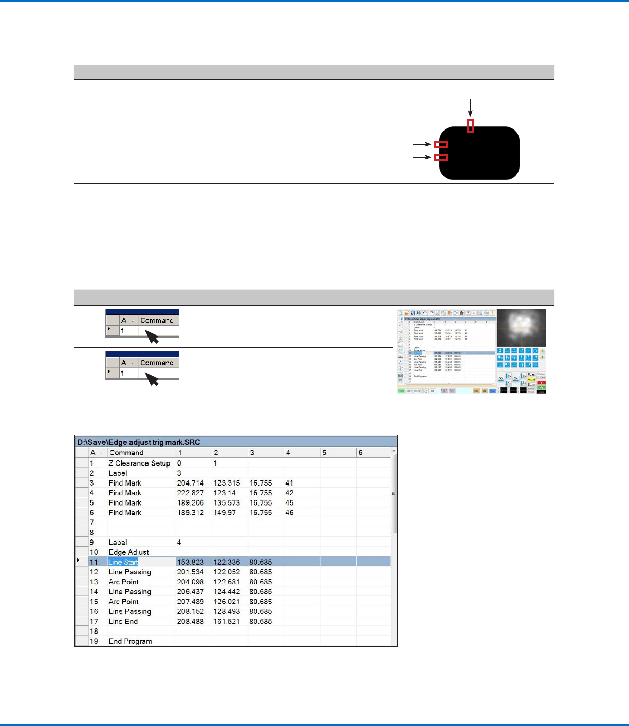
Example program using Edge Adjust and four Find Mark commands
To Use the Edge Adjust Command in a Program
#
Click Step Reference Image
1
• Insert four Find Mark commands near the
top of the program, one for each mark image
created in the previous procedure.
2
• Insert an Edge Adjust command after the Find
Mark commands.
Refer to the sample program provided below
as a guideline.
# Click Step Reference Image
8
• Repeat steps 3–7 to create horizontal
mark 2.
• Repeat steps 3–5 to create vertical
marks 3 and 4. This example uses 40 for
Width and 20 for Height.
3
4
2
9
• Continue to “To Use the Edge Adjust
Command in a Program” on page75.
GV Series Automated Dispensing Systems
76 www.nordsonefd.com info@nordsonefd.com +1-401-431-7000 Sales and service of Nordson EFD dispensing systems are available worldwide.
How to Use Mark Follow to Dispense Along a Curved Line
The Mark Follow and Mark Follow Offset commands are needed when you want the system to dispense along a
curved line.
PREREQUISITES
The system is properly set up. Refer to “Setting Up and Calibrating the System (Required)” on page48.
The system is in the CCD Mode.
To learn how to use this feature, draw a thick, slightly curved line on a sheet of white paper and use it as a
template.
Overview for Dispensing Along a Curved Line
The following tasks are required to cause the system to properly dispense a long a curved line:
• Creating and saving a mark image of a segment of the line. You will also need to know the length of the line.
• Setting up the search range for the mark images.
• Correctly using the Find Mark, Mark Follow, and Mark Follow Offset commands in a dispense program.
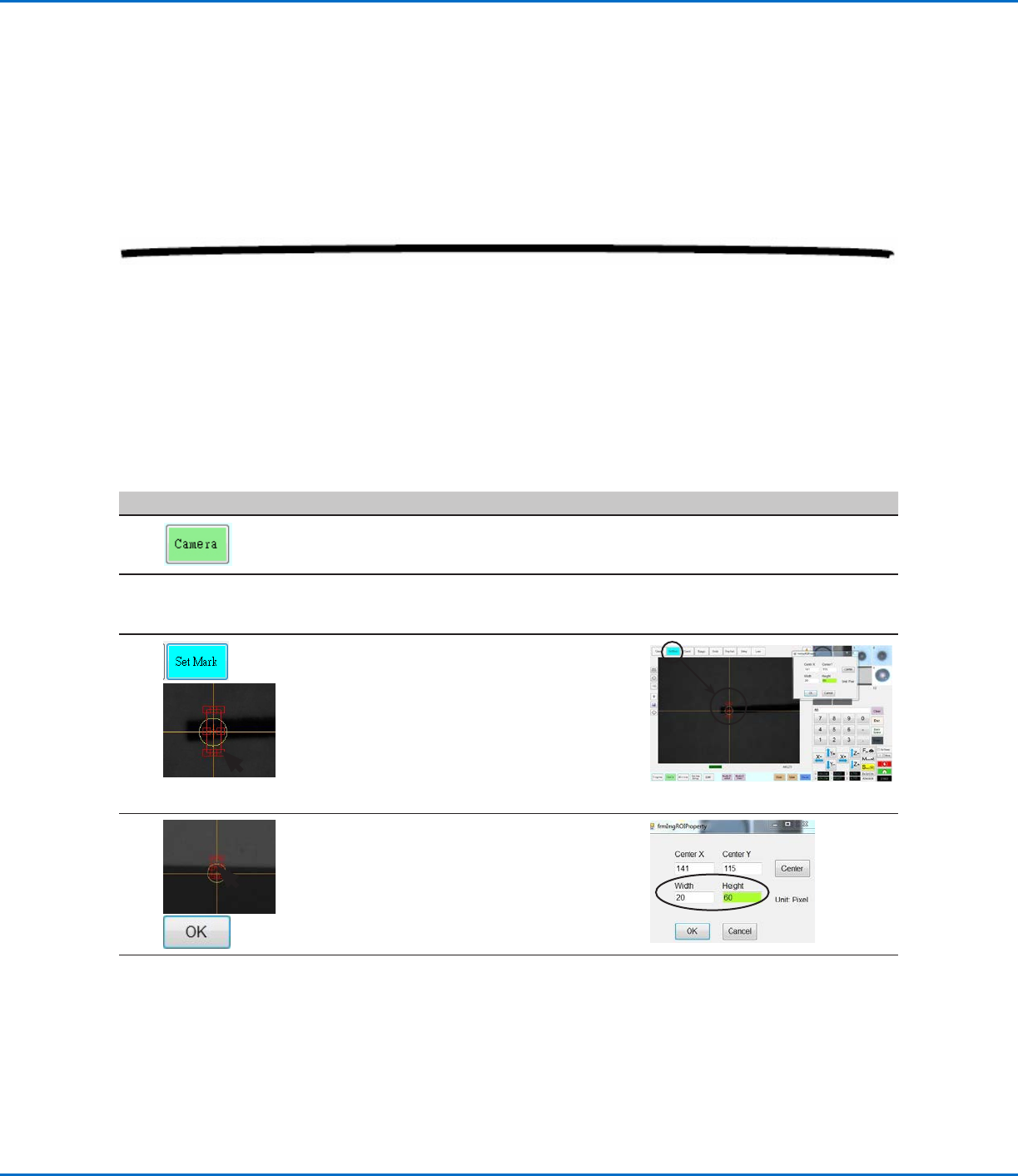
To Create a Mark Image for a Curved Line
# Click Step Reference Image
1
• Click CAMERA to go to the camera
screen.
2
• Bring the image into focus. Refer to
“Camera” on page18 as needed for
instructions on focusing the camera.
3
>
• Click SET MARK, then click and drag
a red rectangle over the first target line
segment on the workpiece.
NOTE: For this example, the mark is
created about 2–3mm (0.8–0.12") from
the left side of line, to allow the system
to find the mark within the specified
range limits when the workpiece is
changed.
4
>
• Double-click the crosshairs in the center
of the red rectangle and then enter the
desired values for Width and Height (20
and 60 in this example).
• Click OK to save the values.
Continued on next page