Nordson_EFD_GV_Series_Operating_Manual.pdf - 第19页
GV Series Automated Dispensing Systems 19 www.nordsonefd.com info@nordsonefd.com +1-401-431-7000 Sales and service of Nordson EFD dispensing systems are available worldwide. Installation Use this section in tandem with t…
GV Series Automated Dispensing Systems
18 www.nordsonefd.com info@nordsonefd.com +1-401-431-7000 Sales and service of Nordson EFD dispensing systems are available worldwide.
Camera
The system includes a precision-vision camera that allows you to view the fixture plate and to focus.
CCD Smart Camera Features How to Focus
Converts the analog camera image
pixels to digital values for extremely
precise image management
• Move the camera up or down to focus
the image.
• If the optional light accessory is
present, use the light controller dial to
adjust the exposure (how much light is
allowed into the image).
Fixed focal length (must move the
camera up and down to focus it)
Variety of lenses available (for different
focal lengths, fields of view, etc.). Refer
to “Accessories” on page89 for the
optional lens kit part number.
Pencil Camera Features How to Focus
Locking
bracket for
focus dial
Location of
screw used
to adjust light
intensity
White
diffuser cap
Combination of manual focus and on /
off dial
To focus the image:
• Without moving the robot, loosen
the screws that secure the focus dial
bracket.
• Turn the focus dial on the camera until
the sharpest image is obtained.
• Tighten the focus dial bracket screws.
To adjust the exposure:
• Use a small Phillips screwdriver to
adjust the camera light such that the
light setting will make the workpiece
surface visible regardless of any
changes in the ambient light.
NOTE: The screw is located inside the
camera housing.
Integrated lighting with an adjustable
light-intensity dial
NOTE: To turn the light off, use a
small flat-blade screwdriver to turn the
screw inside the camera bracket fully
counterclockwise.
White diffuser cap for image
enhancement (can be removed)
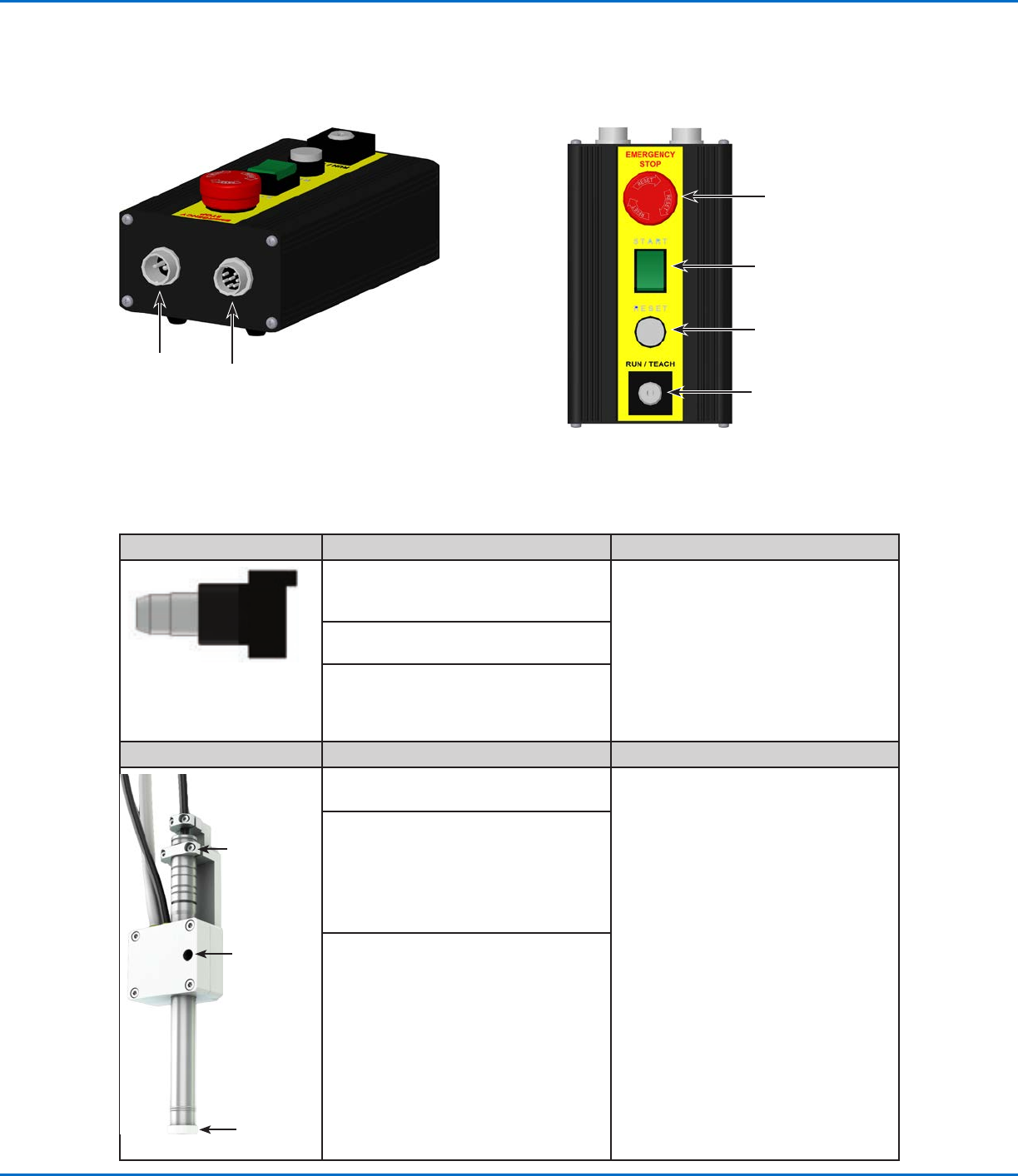
Start / Stop Box
Operating Features (continued)
For the
shorted plug
Connects to Ext.
Control on the
GVoperation box
EMERGENCY STOP
button
START button
RESET button
RUN / TEACH key
GV Series Automated Dispensing Systems
19www.nordsonefd.com info@nordsonefd.com +1-401-431-7000 Sales and service of Nordson EFD dispensing systems are available worldwide.
Installation
Use this section in tandem with the Quick Start Guide and the valve system manuals to install all components of the
system.
Unpack the System Components
WARNING
Unpacking a G4V robot requires a minimum of two
people. Unpacking a G8V robot requires a minimum
of four people. Do not attempt to lift the robot without
assistance.
1. Remove all system components and ship-with
items from the packaging.
2. With assistance, carefully lift the robot by its base
and transfer it to a stable workbench. Never lift the
robot by its cross member.
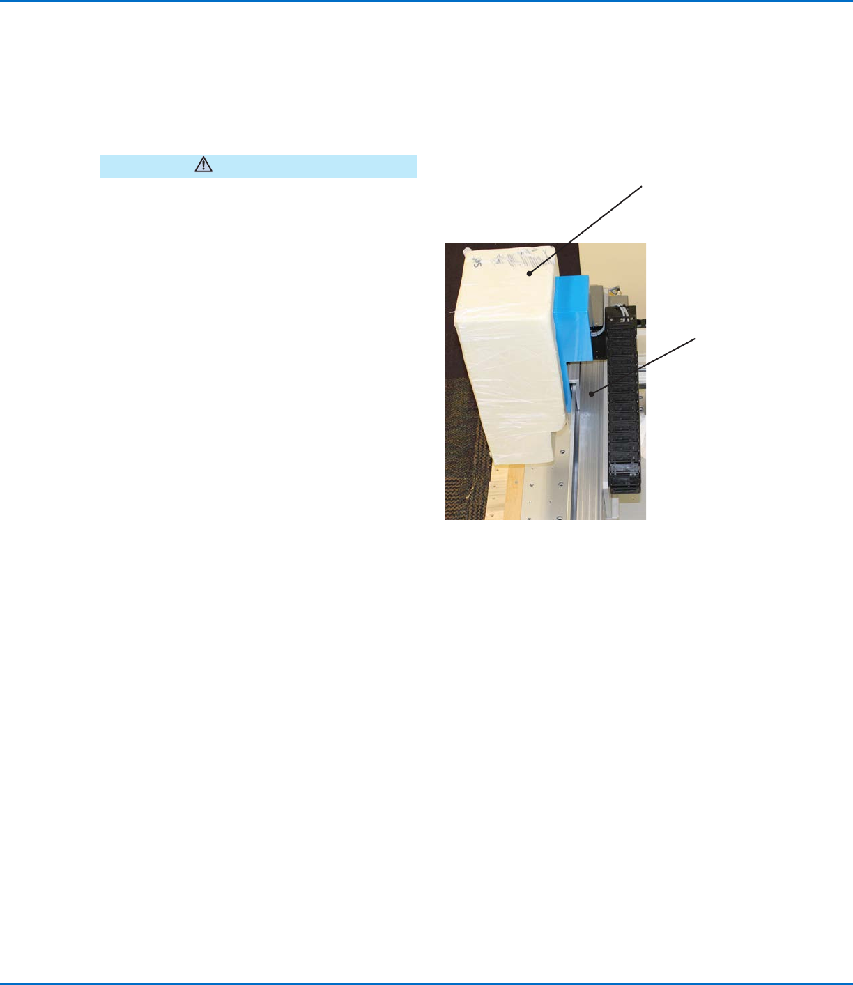
NOTE: All units are shipped from the factory with
foam protectors that secure the worktable to
the X axis and the Zaxis to prevent movement
and damage during shipment. Nordson EFD
recommends retaining all packing material for use if
the robot is shipped or moved in the future.
3. Remove the protective foam covers and tape.
4. Double-check the shipping box to ensure you have
removed everything.
Foam
protector
Cross
member (do
not use to
lift the robot)
GV Series Automated Dispensing Systems
20 www.nordsonefd.com info@nordsonefd.com +1-401-431-7000 Sales and service of Nordson EFD dispensing systems are available worldwide.
Position the Robot and Install and Connect Components
Refer to the Quick Start Guide and to this section as needed to install the system components and make
connections.
NOTES:
• The components of an automated dispensing system vary. Steps for a complete system with all available
components are provided in this manual and in the Quick Start Guide. Perform only the steps that apply to your
system.
• If the system is being used in the European Community, the robot is shipped with an enclosure or light curtain
that (1) prevents an operator from entering the robot’s work area and (2) generates an emergency stop signal if the
enclosure door switch is opened while the robot is running.
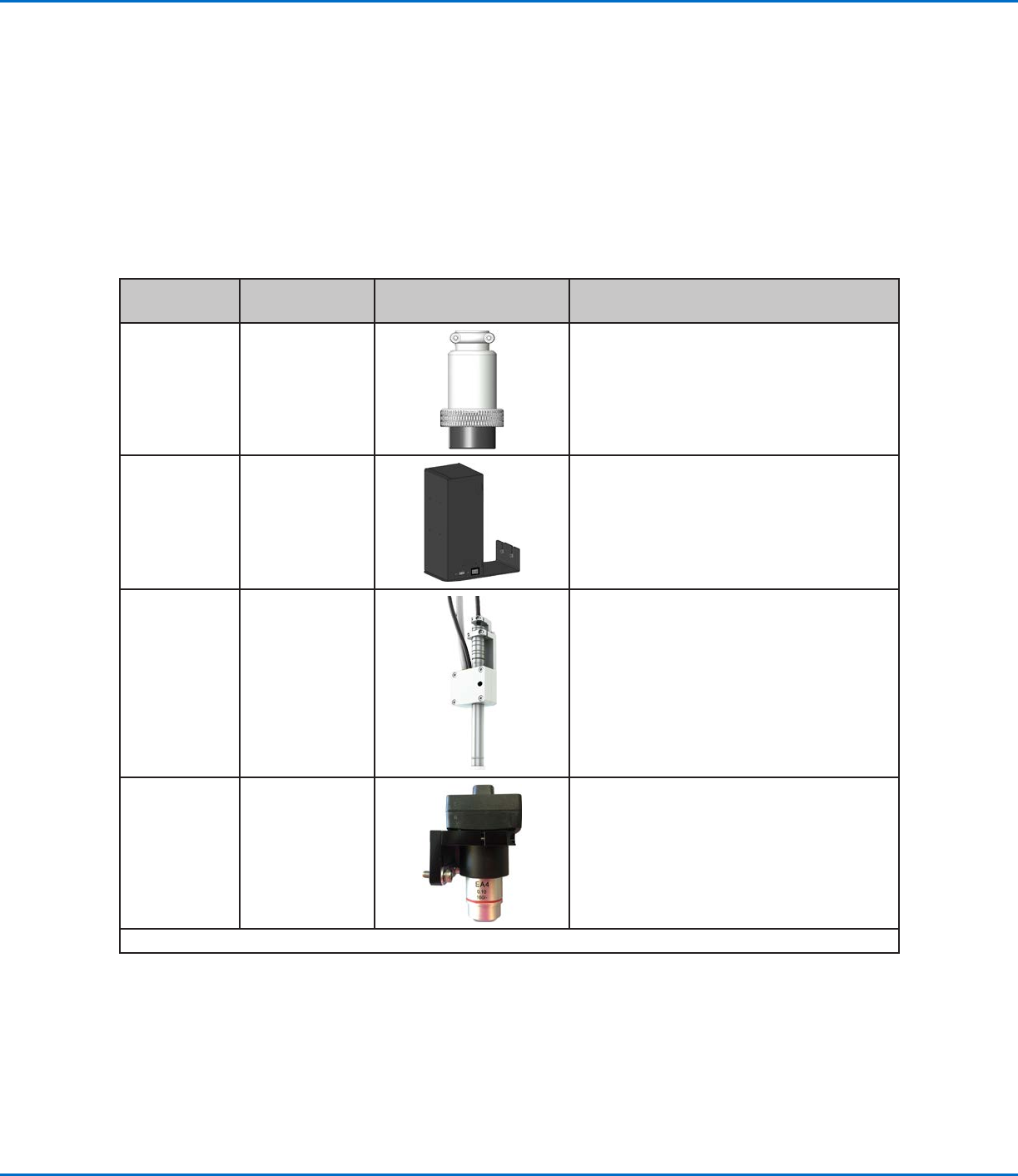
Applicability Item
Components to Install
or Connect
Installation Tasks
All models Input / output
safety plug
(SHORTED)
Connect the 2-pin input / output safety
plug to the 2-pin port on the start / stop
box.
All models DispenseMotion
controller
Mount the DispenseMotion controller on
the shelf.
Install the shelf-and-controller assembly on
the left upright bracket.
Make the connections shown on the Quick
Start Guide.
G4V Pencil camera
Install the bracket.
Install the camera.
Route the camera cable through the
dragon chain on the Z axis.
Secure the cable by using the provided
cable clips to attach it to the Zaxis.
Connect the cable to USB-CCD on the
DispenseMotion controller.
G8V CCD camera
Install the camera and bracket assembly.
Connect the camera cable to the camera.
Route the camera cable through the
dragon chain on the Z axis.
Connect the cable to USB-CCD on the
DispenseMotion controller.
Continued on next page