Nordson_EFD_GV_Series_Operating_Manual.pdf - 第41页
GV Series Automated Dispensing Systems 41 www.nordsonefd.com info@nordsonefd.com +1-401-431-7000 Sales and service of Nordson EFD dispensing systems are available worldwide. Camera Pr operties Window On the Camera tab, C…
GV Series Automated Dispensing Systems
40 www.nordsonefd.com info@nordsonefd.com +1-401-431-7000 Sales and service of Nordson EFD dispensing systems are available worldwide.
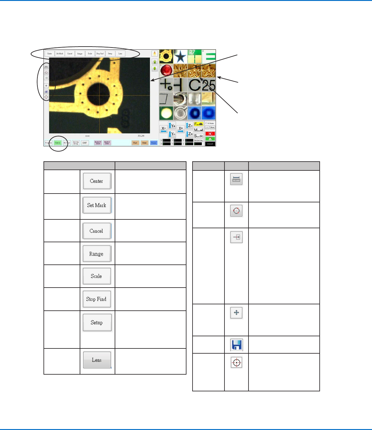
Camera Screen, Tab Bar, and Icons
Click the CAMERA tab to go to the Camera screen. The actual view of what the camera sees appears in the Primary
View screen and the Mark Library appears in the Secondary View screen. The tabs at the top of the Camera screen
are used for camera setup and mark creation.
Camera Screen Tab Function
Center
Moves the camera focal point
to the center of an object
Set Mark
Sets a mark. Refer to “About
Marks” on page28 and to
“How to Create a Mark” on
page70.
Cancel
Cancels the last camera-
related action
Range
Sets the area within which the
system searches for a mark
Scale
Scales the screen to match
the camera view scale (occurs
during setup)
Stop Find
Stops the attempt to find a
mark
Setup
Opens the Camera Setup
window that provides access
to important setup fields
related to the camera. Refer
to “Camera Setup Screen” on
page43.
Lens Opens the Camera Properties
window. Refer to “Camera
Properties Window” on
page41 for details.
Icon Name Icon Function
Measure
Length
Measures the distance
between two points. Refer
to “How to Measure a Path
or Circle on a Workpiece” on
page65.
Measure
Circle
Diameter
Measures the diameter of
a circle. Refer to “How to
Measure a Path or Circle on a
Workpiece” on page65.
Arrow
Accesses advanced
functionality for deposit
verification using the optional
OptiSure
™
add-on software.
This icon is enabled only
when the OptiSure add-on is
unlocked.
Refer to “OptiSure Software
Key” on page91 for the
OptiSure kit part number.
Refer to the OptiSure manual
for operating instructions.
Touch Move
When toggled, moves the
camera to the point clicked
and moves the focal point
to the center of the viewing
screen
Save
Saves the displayed camera
image as a bitmap (*.bmp) file
CCD Focus
Automatically moves the
Zaxis to the focus position
established during Robot
Initial Setup (Step 5 or 6),
or as defined in the camera
setup window (under Offset)
Primary View screen shows the actual
camera view when the Camera tab is
selected
Secondary View screen shows the Mark
Library when the Camera tab is selected
Right-click on any image and then select
PROPERTY to open the Template Match
window. Refer to “Template Match
and Area Windows” on page42 for
information about this window.
GV Series Automated Dispensing Systems
41www.nordsonefd.com info@nordsonefd.com +1-401-431-7000 Sales and service of Nordson EFD dispensing systems are available worldwide.
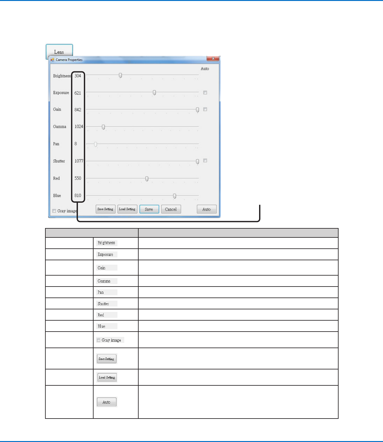
Camera Properties Window
On the Camera tab, Click Lens to open the Camera Properties window. This window provides settings for adjusting
the camera image quality to achieve the sharpest and most useful image.
These parameter values increment or
decrement as you move a slider.
Camera Properties Window Section Function
Brightness
Adjusts the black level of the camera image.
Exposure Controls the amount of light per unit area that reaches the camera.
Gain
Changes the apparent brightness and light-sensitivity of the camera image at a given
exposure.
Gamma
Defines the relationship between a pixel’s numeric value and its actual luminance.
Pan Moves the visible image horizontally and vertically.
Shutter Adjusts the level of light entering the camera.
Red Changes the red levels of the camera image.
Blue Changes the blue levels of the camera image
Gray image Changes the camera image to black and white mode
Save Setting
Saves the displayed Lens settings as a *.ccd file (CCD parameter file). Each *.ccd file
can have its own unique Lens settings. When a new mark image is created, it will use
the current Lens settings.
Load Setting
Allows you to load the Lens settings from a saved *.ccd file. When the settings are
loaded, click SAVE to make them the current settings.
Auto
Attempts to generate the most optimal settings depending on the amount of light
present. Clicking the checkbox next to the property indicated (Exposure, Gain, or
Shutter) locks that property so that it cannot be edited using the slider. However, these
settings can be adjusted by the system when you click the AUTO button regardless of
whether they are locked.
GV Series Automated Dispensing Systems
42 www.nordsonefd.com info@nordsonefd.com +1-401-431-7000 Sales and service of Nordson EFD dispensing systems are available worldwide.
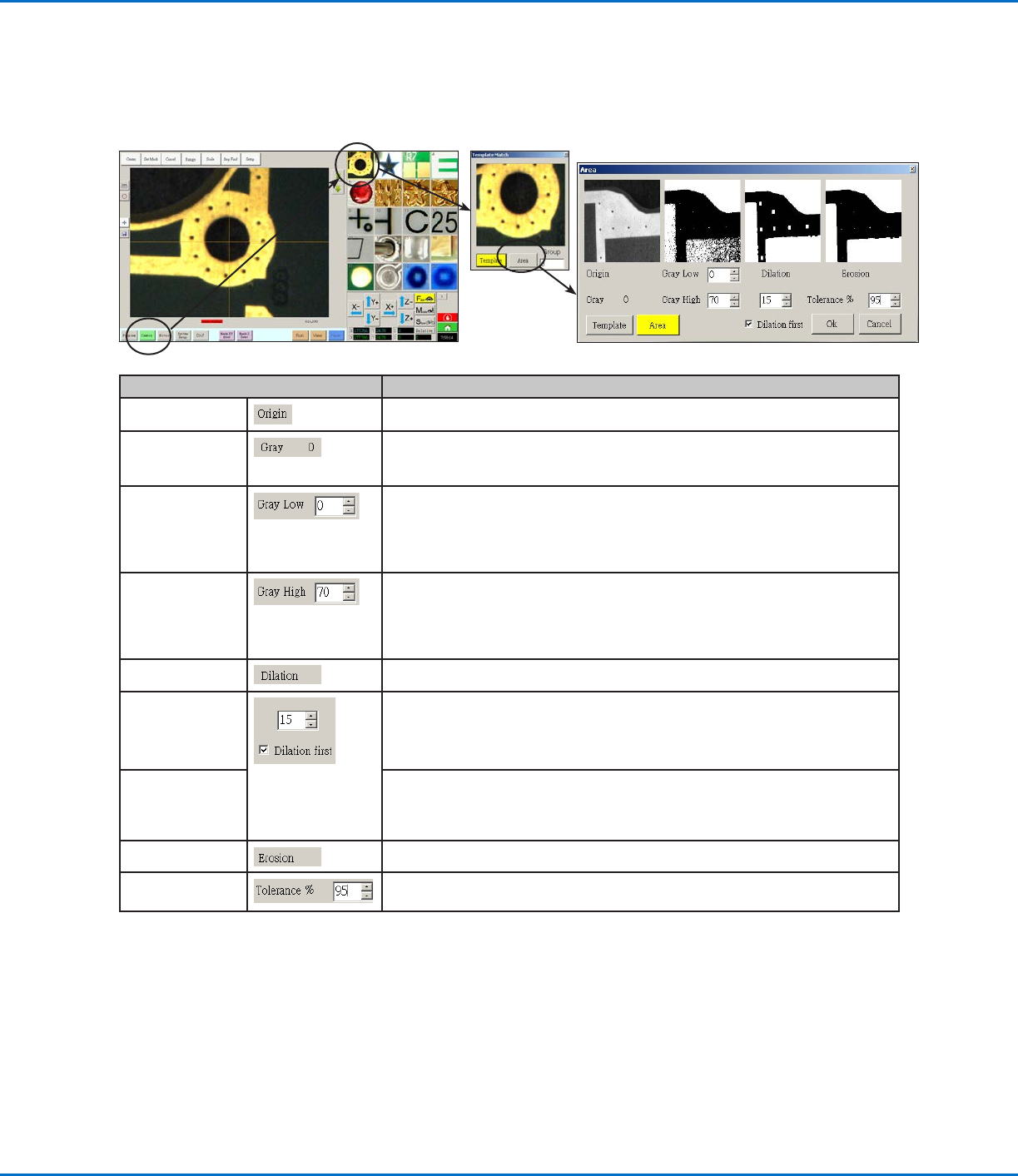
Template Match and Area Windows
Once a mark is stored in the Mark Library, you can right-click on the mark image cell and select PROPERTY to open
the Template Match window. The Template Match window provides access to the Area window, which is used to
fine-tune how the camera evaluates a mark.
Template Match Area Window Section Function
Origin
Displays the open mark image.
Gray Displays the gray rating for the selected point in the original image. When a point is
selected, the value changes to reflect the gray level at that point. Knowing this value
makes it easier to determine the best Gray Low and Gray High values to set.
Gray Low
Adjusts the gray low-tolerance value. The lower the value, the more white is
tolerated in the image. The higher the value, the less white is tolerated in the image.
NOTE: Gray Low values are typically lower than Gray High values.
Range: 0–255
Gray High
Adjusts the gray high-tolerance value. The lower the value, the less white is tolerated
in the image. The higher the value, the more white is tolerated in the image.
NOTE: Gray High values are typically higher than Gray Low values.
Range: 0–255
Dilation
Displays how the image appears after the Dilation calculation.
Dilation First
counter
When Dilation First is checked, the counter above the Dilation First checkbox
controls the zoom of the image. When Dilation First is unchecked, the counter
controls how much of the non-gray areas in the image are ignored.
Range: 0–20
Dilation First
checkbox
Sets the order in which the dilation and erosion calculations are performed. If the
Dilation First checkbox is checked, the system performs the dilation calculation first.
If the checkbox is unchecked, the system performs the erosion calculation first.
When Dilation First is unchecked, the Dilation and Erosion labels switch places.
Erosion
The image above Erosion shows how much white is filtered from the image.
Tolerance Sets the tolerance for how similar other mark images can be to the selected image,
allowing the system to eliminate similar marks.