Nordson_EFD_GV_Series_Operating_Manual.pdf - 第146页
GV Series Automated Dispensing Systems 146 www.nordsonefd.com info@nordsonefd.com +1-401-431-7000 Sales and service of Nordson EFD dispensing systems are available worldwide. IO Pin Function Configurations Input Configura…
GV Series Automated Dispensing Systems
145www.nordsonefd.com info@nordsonefd.com +1-401-431-7000 Sales and service of Nordson EFD dispensing systems are available worldwide.
Appendix F, Height Sensor Setup and Use (continued)
To Use the Height Sensor Capability
PREREQUISITES
The system is properly set up. Refer to “Setting Up and Calibrating the System (Required)” on page48.
The height sensor is installed, enabled, and set up. Refer to “To Enable the Height Sensor” on page142 and to
“To Set Up the Height Sensor” on page142.
The program you want to edit using the height sensor capability is open.
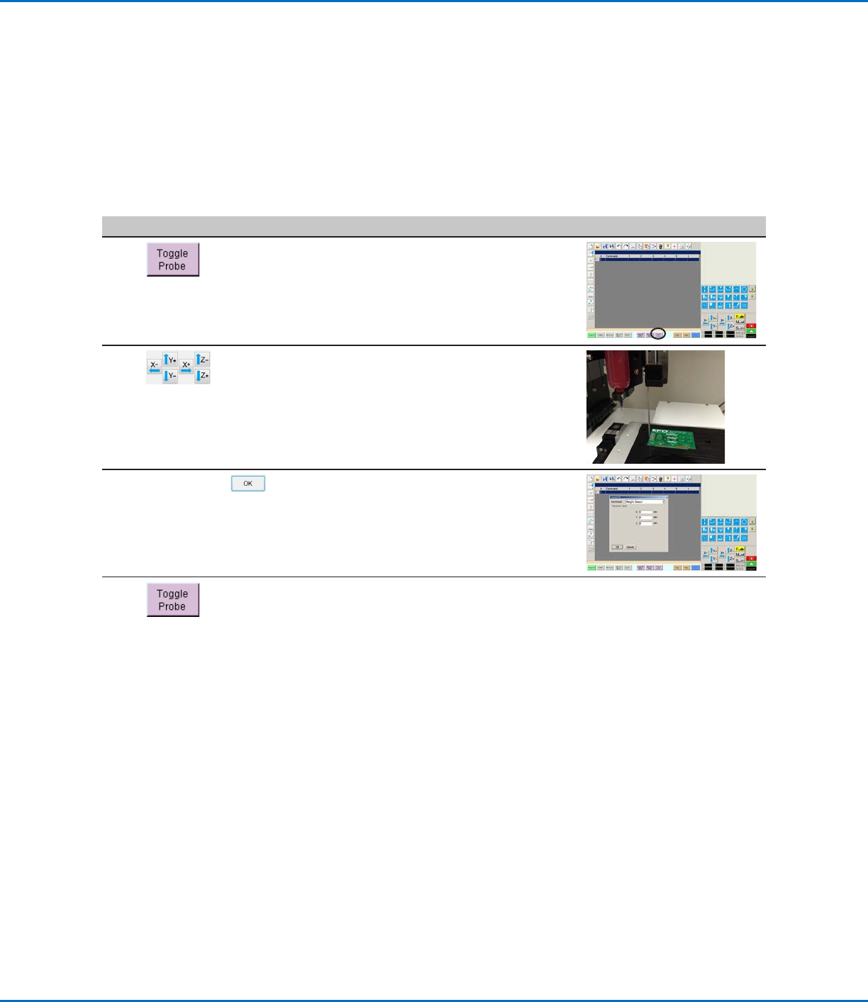
# Click Step Reference Image
1
• Click TOGGLE PROBE.
The probe extends from the height
sensor.
2
• Jog to the location where the system
should check the height for each
workpiece.
• Use the Z jog keys to lower the
probe to approximately 10 mm (0.4")
above the target location on the
workpiece.
3
HEIGHT SENSOR >
• Double-click the address row where
you want to insert a Height Sensor
command and then select HEIGHT
SENSOR from the drop-down menu.
• Click OK to accept the XYZ values.
4
• Click TOGGLE PROBE to retract the
probe.
The system will now check the
workpiece height each time the
programs runs.
GV Series Automated Dispensing Systems
146 www.nordsonefd.com info@nordsonefd.com +1-401-431-7000 Sales and service of Nordson EFD dispensing systems are available worldwide.
IO Pin Function Configurations
Input Configuration Description
Input Default setting.
Start A signal to start the execution of the dispense program.
Door A signal to stop the execution of the dispense program. This configuration is to be used in
tandem with the DOOR OPEN output configuration.
Stop A signal to stop the execution of the dispense program.
Home A signal to home / reinitialize the robot after a stop of the dispense program.
Table Ready A signal to indicate that the system is ready to execute the dispense program. The dispense
program will not execute if the input signal is off. This configuration is to be used in tandem with
the TABLE READY output configuration.
Pause A signal to pause the execution of the dispense program.
Call Program A signal to initiate a different program. Use the Call Program selection from the Expert menu to
specify the program to call.
XY Adjust A signal to initiate Needle XY Adjust.
Z Detect A signal to initiate Needle Z Detect.
Output Configuration Description
Output Default setting.
Emergency A signal indicating that the robot has stopped.
EMG-B A signal indicating that the Emergency Stop button on the robot is pressed.
Running A signal indicating that the dispense program is currently executing.
Homing A signal indicating that the robot is reinitializing / moving to home position.
Standby A signal indicating that the robot is in a standby (idle) position.
Pause A signal indicating that the dispense program is paused.
System Start A signal indicating that the DispenseMotion software is open and running.
Table Ready A signal indicating that the system is ready to execute the dispense program. This configuration
is to be used in tandem with the TABLE READY input configuration.
Door Open A signal indicating that the door is open. This configuration is to be used in tandem with the
DOOR input setting.
No Start Trigger A signal indicating that the program cannot run until the TABLE READY input signal is ON.
When the TABLE READY input is ON, the NO START TRIGGER indication switches OFF.
This configuration must be used with the TABLE READY input and the TABLE READY output
configurations.
Teach Mode A signal indicating that the robot is in the Teach mode. This signal can be used when the
external start / stop box is present.
Calibration Execution A signal indicating that the robot is performing a Needle Z Detect or a Needle XY Adjust.
Positional Error A signal indicating an over-limit warning after a general over-limit warning from program
execution occurs.
In Home A signal indicating that the tip is in the Park Position.
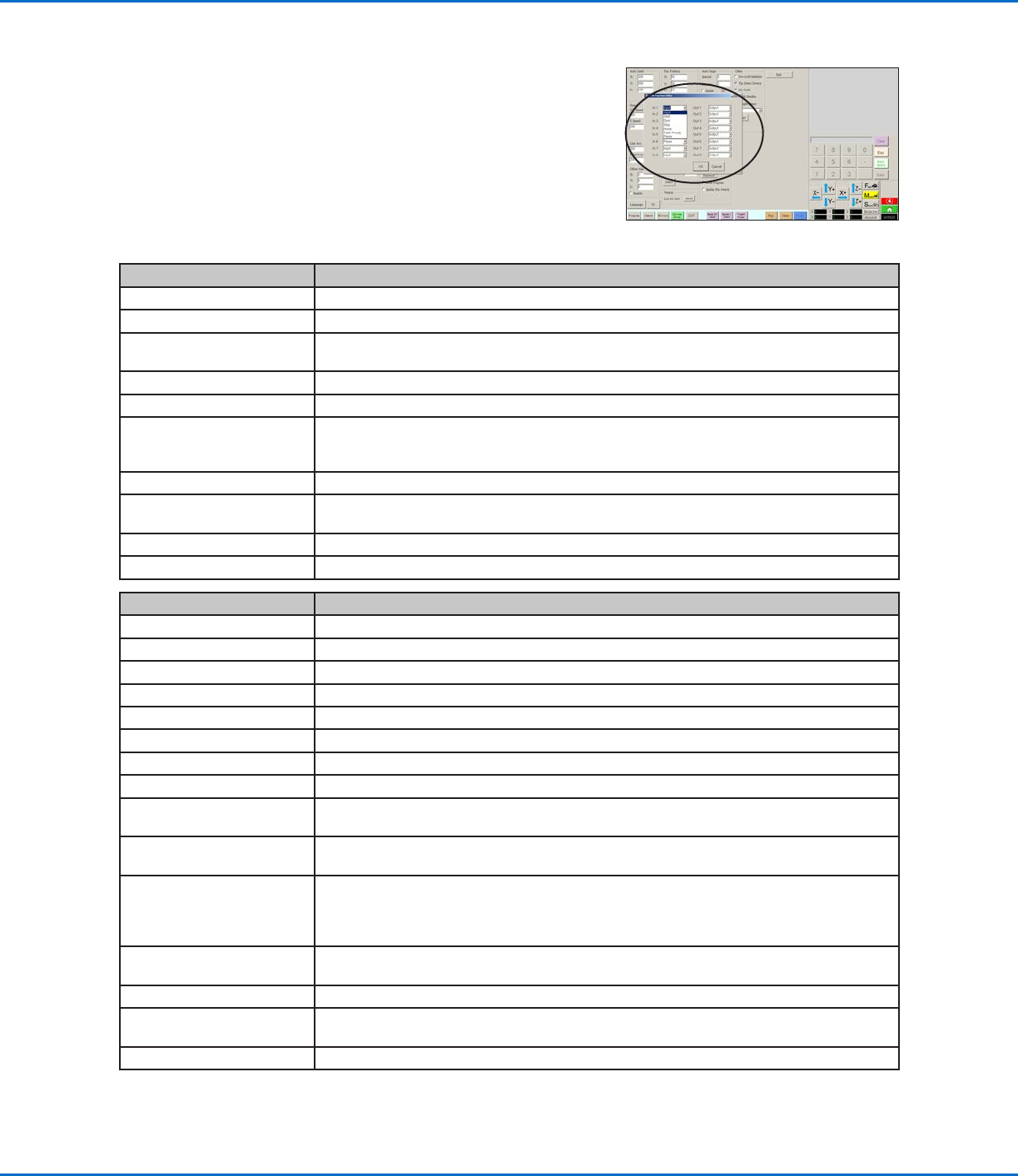
AppendixG, I/O Pin Function Setup
The I/O Pin Function capability, accessed through the Expert menu on the
System Setup screen, provides a set of user-configurable conditions that
can be assigned to the available inputs and outputs on the I/O Port. These
conditions affect the operation of the robot.
GV Series Automated Dispensing Systems
147www.nordsonefd.com info@nordsonefd.com +1-401-431-7000 Sales and service of Nordson EFD dispensing systems are available worldwide.
To Reconfigure Inputs / Outputs
PREREQUISITES
The system is properly set up. Refer to “Setting Up and Calibrating the System (Required)” on page48.
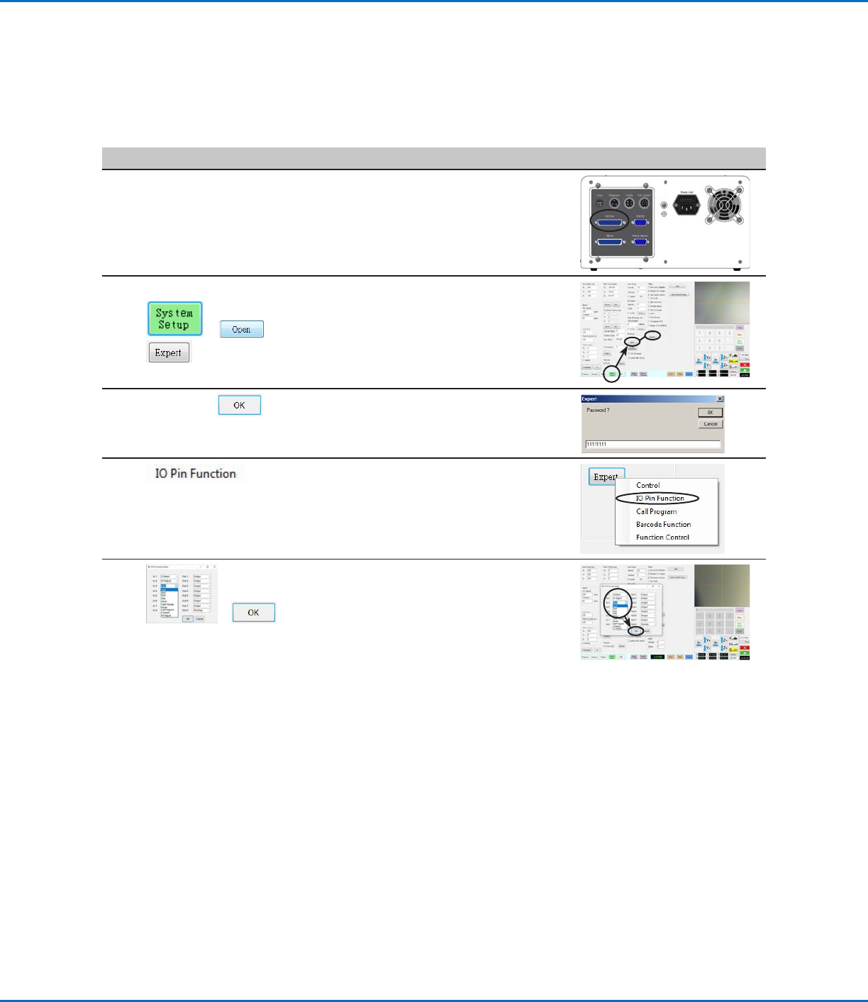
#
Click Step Reference Image
1
• Connect the signal wiring to the I/O
Port on the back of the GV operation
box.
2
> >
• Click SYSTEM SETUP > OPEN >
EXPERT.
3
11111111 >
• Enter 11111111, then click OK.
4
• Click IO PIN FUNCTION.
5
>
• Click the input or output to configure,
then select the configuration from the
drop-down menu. Refer to “IO Pin
Function Configurations” on page146
for a description of the configuration
selections.
• Click OK.
Appendix G, I/O Pin Function Setup (continued)