CP7 training(6.0) (1).pdf - 第100页
FK-9F98-27 CP-7 Series Traini ng Text for Service Engineers Edition 6.0 Chapter 6. Servo Pack Zero Ad justment and Gain / Motion Check [4/10] 4. Release th e emergency stop button , pres s [Ready ON] to turn the servo po…
FK-9F98-27 CP-7 Series Training Text for Service Engineers
Edition 6.0 Chapter 6. Servo Pack Zero Adjustment and Gain / Motion Check [3/10]
6.3 Servo Pack Zero Setting Operation
Servo Pack zero setting is performed in two stages (Auto and Manual). Follow the procedure
below carefully. This procedure is done to set the zero stability point of the servo pack.
Note: Carry out the adjustment for each axis in the same manner
.
Auto Zero Setting
1. Press the M/C emergency button to turn the servo power OFF. Auto zeroing must be
done with the E-Stop pressed.
2. Press [MODE/SET] (on the Servo Pack control panel) Æ to display <Fn000> Æ Press the
[ ] key 9 times to Display <Fn009> Æ Press [DATA/SHIFT] for more than 1 second. Æ
Display <rEF_0> Æ Press [Mode/Set] for more than 1 second. Æ <done> will display for 1
second and return to <rEF_0> Æ Press [DATA/SHIFT] for more than 1 second. Æ The
display will return to <Fn009> Æ Press [MODE/SET] 3 times to display < bb>. The
procedure for auto zero setting is now complete. (Note: Carry out the adjustment for each
axis in the same manner.)
Manual Zero Setting
1. Return to Fig.3 and press [Servo Check] to enter the servo check command.
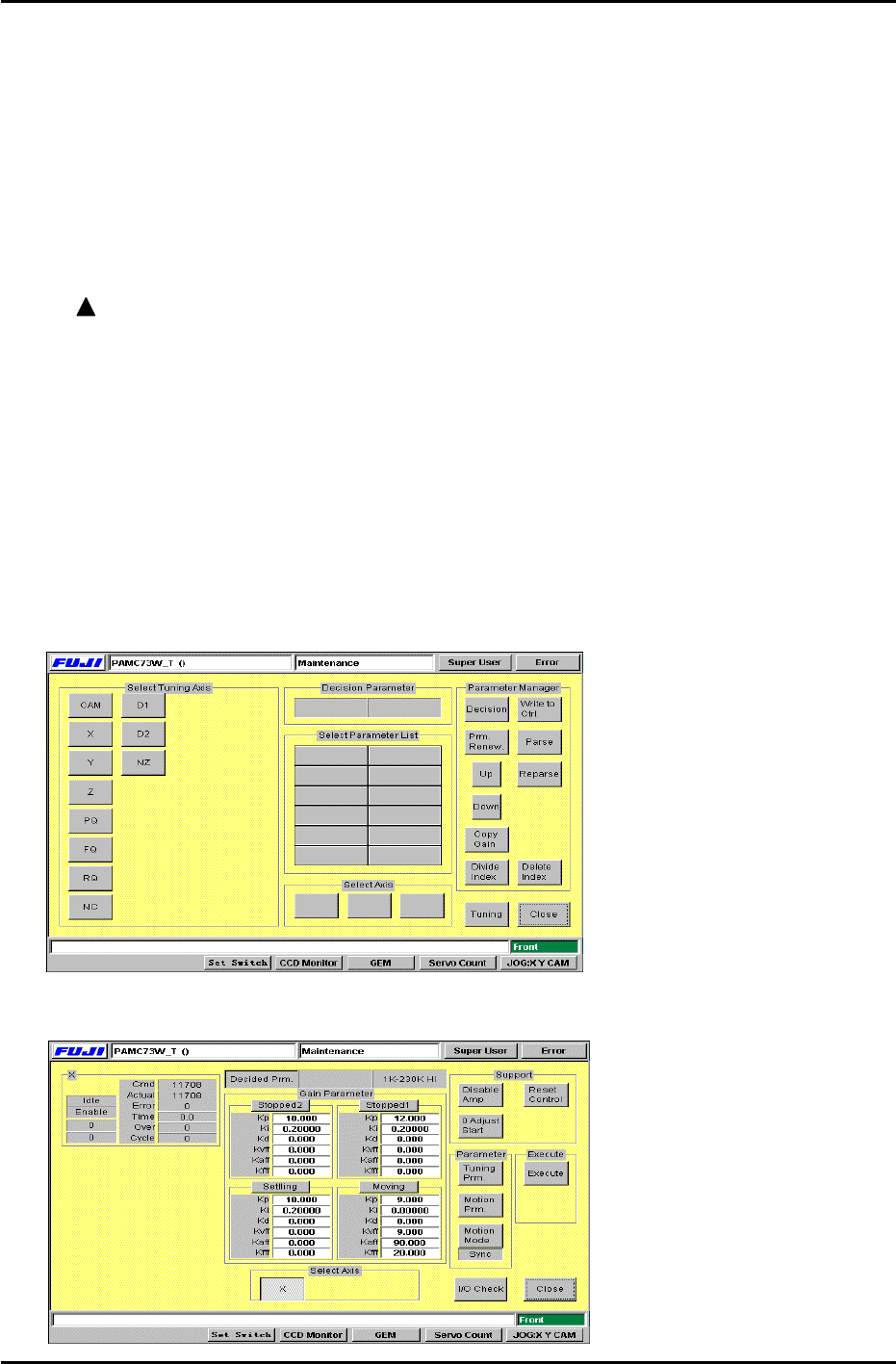
2. After the display changes to Fig.4, select the axis to be adjusted from [Select Tuning
Axis]. Press again to cancel if necessary.
[Note]: Select only one axis from [Select Tuning Axis] at a time.
Figure 4
3. Press [Tuning] and the display will change to Fig.5.
Figure 5
Fuji Machine Mfg. Co., Ltd. (Okazaki)
SMT Equipment Quality Assurance Dept.
CS Section
6-3

FK-9F98-27 CP-7 Series Training Text for Service Engineers
Edition 6.0 Chapter 6. Servo Pack Zero Adjustment and Gain / Motion Check [4/10]
4. Release the emergency stop button, press [Ready ON] to turn the servo power ON.
5. Press [0 Adjust Start] (fig. 5) and the M/C [Start] button will begin to blink.
When the [Start] button is pressed, servo pack zero setting will start. If the counter value in
[Actual] (fig. 5) is not stable, carry out the adjustment as follows so that the value remains
relatively constant.
Press [MODE/SET] Æ Display <Fn000> Æ Press the key 10 times to display <Fn00A> Æ
Press [DATA/SHIFT] more than 1 second. Æ < SPd> Æ Press [DATA/SHIFT] (less than 1
second) Æ Display <Speed Command Offset>
Press the keys, in order to stabilize the servo counter value. [see “Actual” on the
screen] Æ when the counter value stabilizes, press [DATA/SHIFT] (for less than 1 second.)
Æ to display < SPd> Æ Press [DATA/SHIFT] for more than 1 second. (Data will be
recorded). Æ Return to <Fn00A>. Æ Press the emergency button to turn the servo OFF. Æ
Press the [MODE/SET] button 3 times to display < bb>.
Manual zero setting is now complete.
6. Carry out adjustment for each axis in the same manner.
[Note]: Always push the emergency button when stopping zero adjustment.
Fuji Machine Mfg. Co., Ltd. (Okazaki)
SMT Equipment Quality Assurance Dept.
CS Section
6-4

FK-9F98-27 CP-7 Series Training Text for Service Engineers
Edition 6.0 Chapter 6. Servo Pack Zero Adjustment and Gain / Motion Check [5/10]
6.4 Servo Pack Gain and Motion Check
Cautions to be observed during the Gain and Motion Check
1. Check that each axis fits into the time and overshoot amount.
2. The parameter for each axis, the value to enter into [Start] [End], the traverse time, and the
overshoot amount is listed in the gain test adjustment table.
3. Basically, parameters (Pn100, 101, 401) are fixed. If the motion value is not in range, check again
after idling. If problems persist contact Fuji for further instructions.
Check that the conditions are met for each axis as described below
[C-axis]
1. The I/O is set as described on page 6-2.
2. In [Start], enter the counter value when the cam is at 0 degrees (present position). In [End],
enter “Start value + 12000”. The counter value for the current position shows next to Actual
on the left side of the display.
[X, Y-axes]
1. The main table is moved to the unloading position.
2. The cam angle is 0 degrees
3. The Z-axis is lowered, and the main lifter is clamped.
4. Check both parameters listed on the Gain Test table for the X, & Y-axes.
[Z-axis]
1. The main lifter is clamped.
[PQ, FQ, RQ, NC-axes]
1. Use the Parts Rejection command and make sure the shafts are all facing the correct direction.
After checking the [Rot100] parameter at a cam angle of 180 degrees, check the [Rev]
parameter at cam angle 0 degrees. When adjusting [Rot100], make sure that the clutch is
properly engaged with the shaft.
[D1, D2-axes]
1. Make sure both Device pallets are retracted
2. The D-axis pallet is lowered
3. The cam angle is at 0 degrees
4. The D-axis stoppers are both retracted.
5. Check both parameters listed on the Gain Test table for the D-axes.
[NZ-axis]
1. Check at a cam angle of 0 degrees.
Fuji Machine Mfg. Co., Ltd. (Okazaki)
SMT Equipment Quality Assurance Dept.
CS Section
6-5