CP7 training(6.0) (1).pdf - 第38页
FK-9F98-27 CP-7 Series T raini ng T ext for Service Engineers Edition 6.0 Chapter 3. X, Y , Z and D-axes Adjustm ent [24/36] 8. The following table list s the D axis Calibration Data and physi cal data referen ce values:…
FK-9F98-27 CP-7 Series Training Text for Service Engineers
Edition 6.0 Chapter 3. X, Y, Z and D-axes Adjustment [23/36]
CP-732/733E
D Axis Calibration Data Item (D2) Reference Value
(0.002mm/pulse)
− Mechanical Stopper − 5000 +/- 50
− OT Sensor ON − 1500 +/- 50
Min Limit Position D2
− 1000 +/- 50
D2 Original Position 0 +/- 1000
Pick up position T2 (264300)
Max Limit Position D2 507000 +/- 1000
+ OT Sensor ON 507500 +/- 1000
+ Mechanical Stopper 508500 +/- 1000
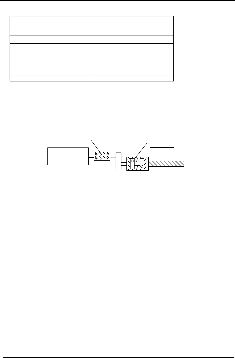
3.12.2 CP-742/743E Supplementary Procedure
The method of locking the coupling is slightly different on the CP-742/743E and is described
below. For the basic procedure, please refer to section 3.12.1.
Coupling 2
MOTOR
Coupling 1
Figure 29
1. Ensure that the D table is against the mechanical stopper.
2. Lock the two right hand bolts of Coupling 1 with an 8.3N.m torque wrench and long 5mm
attachment.
3. Lock the two left hand bolts of Coupling 2 with a 67.6N.m torque wrench and 10mm
attachment.
4. Lock the two left hand bolts of coupling 1 with an 8.3N.m torque wrench and long 5mm
attachment.
5. Rotate Coupling 2 by hand until the pulse count is 5000 pulses (D1). – 5000 pulses (D2).
6. Turn the servo ON.
7. Finally, Lock the two right hand bolts of Coupling 2 with a 67.7N.m torque wrench and 10mm
attachment.
Fuji Machine Mfg. Co., Ltd. (Okazaki)
SMT Equipment Quality Assurance Dept.
CS Section
3-23
FK-9F98-27 CP-7 Series Training Text for Service Engineers
Edition 6.0 Chapter 3. X, Y, Z and D-axes Adjustment [24/36]
8. The following table lists the D axis Calibration Data and physical data reference values:
CP-742/743E
D Axis Calibration Data Item (D1) Reference Value
(0.002mm/pulse)
+ Mechanical Stopper 5000 +/- 50
− OT Sensor ON
1500 +/- 50
Max Limit Position D1 1000 +/- 50
D1 Original Position 0 +/- 1000
Pick up position T1
(
−1150700)
Minimum Limit Position D1 – 1153500 +/- 1000
+ OT Sensor ON
− 1154000 +/- 1000
− Mechanical Stopper
− 1157500 +/-1000
CP-742/743E
D Axis Calibration Data Item (D2) Reference Value
(0.002mm/pulse)
− Mechanical Stopper − 5000 +/- 50
− OT Sensor ON − 1500 +/- 50
Min Limit Position D2 – 1000 +/- 50
D2 Original Position 0 +/- 1000
Pick up position T2 (591300)
Max Limit Position D2 1153500 +/- 1000
+ OT Sensor ON 1154000 +/- 1000
+ Mechanical Stopper 1157500 +/- 1000
3.12.3 D-axis Pallet and Interference Prevention Sensor Adjustment
Note: Whenever moving the D table up and down, the D axis servo count must be at or very
close to zero. It is very important that the D table is positioned correctly in relation to
the lifter. If not, a crash may occur. Also, check that the lifters are at their lower limit
whenever moving the D tables along the D-Axis.
(Part 1) - Speed Controller Setting (all CP7 Series)
1. Move the D tables toward the center of the D axis; well away from the D original position.
2. Temporarily set the lifter UP and lifter Down flow controls:
CP-742/743(M)E CP-732/733E
UP 6 x from fully closed 4.5 x from fully closed
DOWN 3.5 x from fully closed 5 x from fully closed
UP
Down
Figure 30
Fuji Machine Mfg. Co., Ltd. (Okazaki)
SMT Equipment Quality Assurance Dept.
CS Section
3-24
FK-9F98-27 CP-7 Series Training Text for Service Engineers
Edition 6.0 Chapter 3. X, Y, Z and D-axes Adjustment [25/36]
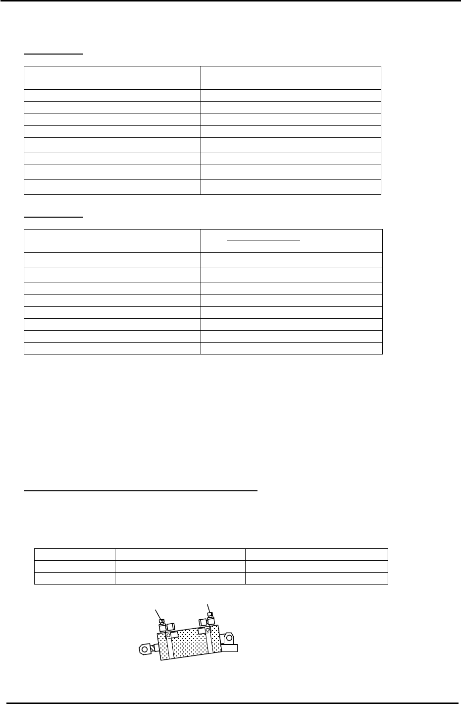
3. Set the 4 PCU Unit Clamp and Unclamp flow controls, 5 x from fully closed then lock.
(A) PCU flow controls
Pallet Up/Down control
PCU Clamper L
PCU Clam
p
er R
Figure 31
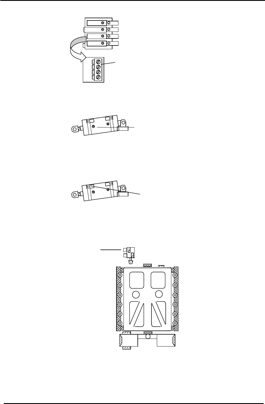
Table Stopper Cylinder control
4. Set the D cam cylinder cushioning adjustment screws, 2 x from fully closed, then lock.
Cylinder cushion
adjustment screws.
Figure 32
5. Set the D cam cylinder Upper and Lower Limit Check sensors 0.5mm toward the ON position.
Cylinder check sensors
Figure 33
6. Set the D table notch stopper flow controls 3 x from fully closed then lock.
Notch stopper flow controls
Figure 34
Fuji Machine Mfg. Co., Ltd. (Okazaki)
SMT Equipment Quality Assurance Dept.
CS Section
3-25