CP7 training(6.0) (1).pdf - 第26页
FK-9F98-27 CP-7 Series T raini ng T ext for Service Engineers Edition 6.0 Chapter 3. X, Y , Z and D-axes Adjustm ent [12/36] 3.8 X/Y T able Leveling Equipment Checklist 0.3mm feeler gauge 0.03mm feeler gauge 3mm L-wrench…
FK-9F98-27 CP-7 Series Training Text for Service Engineers
Edition 6.0 Chapter 3. X, Y, Z and D-axes Adjustment [11/36]
3.7.2 X0/Y0 Calibration Data Measurement for CP-732/733E
Equipment Checklist:
1- X0/Y0 origin pin jig
1- X0/Y0 special dial gauge set up
1- 3mm L-wrench
1- Small mirror
1. Remove the first claw on the right side of the reference rail.
2. Install the pin holder jig on the reference rail. Make sure that it is pulled up against the right edge of
the reference rail.
3. With the cam at 0 degrees use the I/O to turn the 9th station place solenoid OFF. (Y034)
4. Remove holders: A, B & P and attach the X0/Y0 special dial gauge set up on shaft A.
(Jig No.:ADCPJ8080 )
Pin Holder Jig
(Jig No.:ADCPJ8090 )
Figure 10
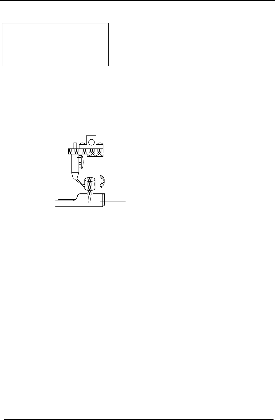
5. Insert the reference pin jig into the pin holder jig.
6. Measure with the cam angle at 180 degrees.
7. Press the emergency stop button so the machine goes to a servo down condition.
8. Make sure the Z- axis is at its lower limit.
9. Move the XY table manually until the reference pin jig meets the dial gauge on the A holder.
10. Move the table very carefully by hand until you find the point where the dial gauge is zero (or closest
to zero) throughout the circumference of the reference pin jig.
11. When the position is established, enter it into Calibration Data as follows:
Press: [Maintenance] → [Calibration] → [Placing Reference] → [X0/Y0] → [Set]
12. Finally, remember to remove the dial gauge and jig, but leave the reference pin out until after the
next adjustment: 3.8 XY Table Level Check.
Fuji Machine Mfg. Co., Ltd. (Okazaki)
SMT Equipment Quality Assurance Dept.
CS Section
3-11
FK-9F98-27 CP-7 Series Training Text for Service Engineers
Edition 6.0 Chapter 3. X, Y, Z and D-axes Adjustment [12/36]
3.8 X/Y Table Leveling
Equipment Checklist
0.3mm feeler gauge
0.03mm feeler gauge
3mm L-wrench
Dial Gauge
Mini Minus Driver
4mm T-wrench
Calculator
2N.m torque wrench with 2.5mm attachment
3.8.1 (Part 1) Table Leveling
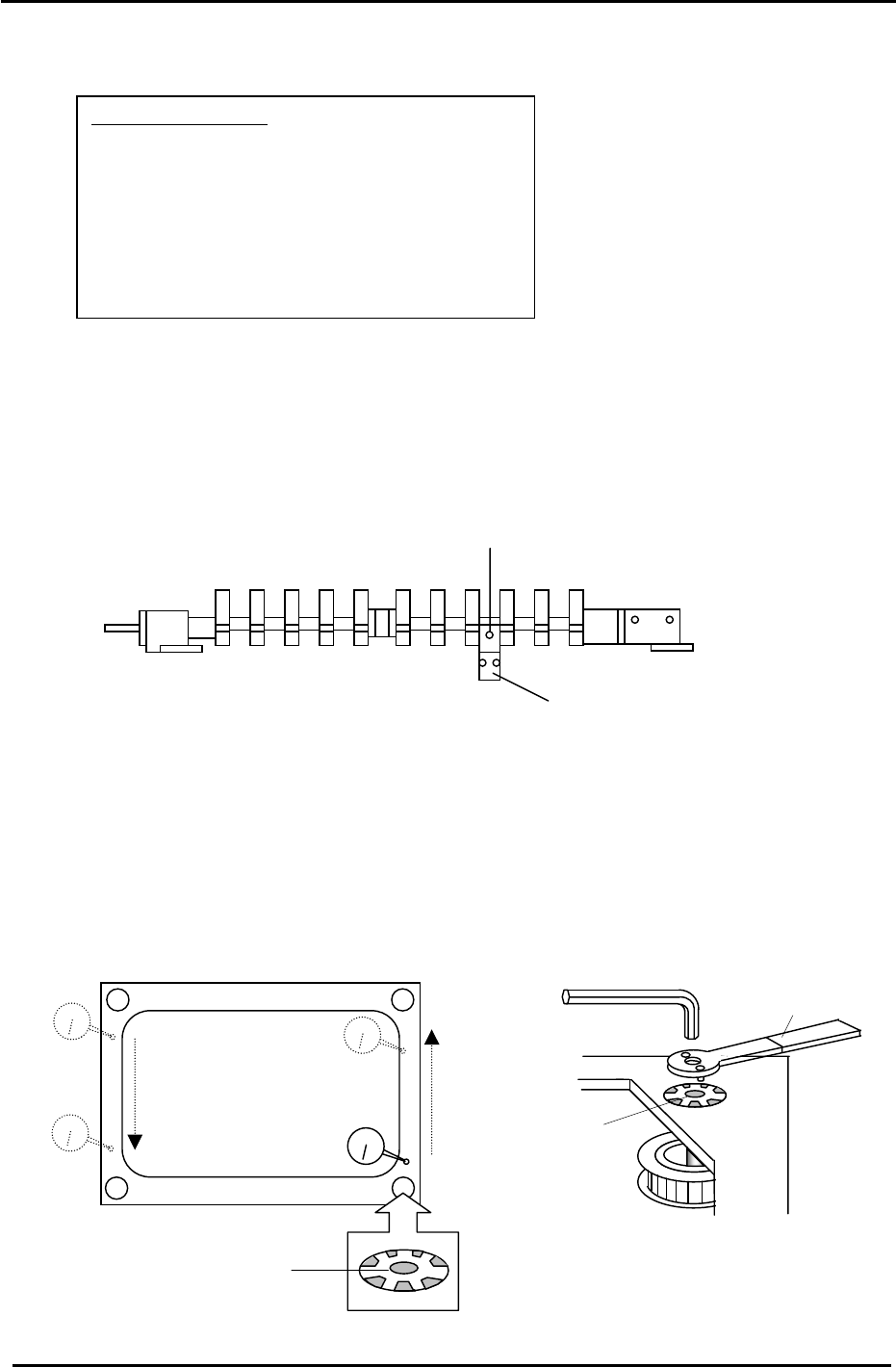
1. Loosen all of the XY table Pcb clamping claws with a 3mm wrench.
2. Loosen the sensor flag base and remove the sensor flag from the fixed rail. (Fig.11)
(CP-742/743(M)E)
Figure 11
Sensor Flag (CP-742/743(M)E)
Sensor Flag Base (CP-742/743(M)E)
3. With the cam angle at 0 degrees, release the air and set the gap between the reference and
adjustable rails at a position adequate for setting the dial gauge.
4. Reconnect the air and clamp the two rails.
5. (Initial Leveling) Level the table as illustrated below by loosening the four corner lock nuts
and adjust the table flatness (at the points indicated) to be within 0.1mm. After completion,
ensure the lock nuts are securely tightened. Then, apply Three Bond 1320N to the four lock
nut locations as indicated in Fig.12.
Jig No.:DCPJ0700
Apply Three Bond
1320N here
Figure 12
Lock Nut
Fuji Machine Mfg. Co., Ltd. (Okazaki)
SMT Equipment Quality Assurance Dept.
CS Section
3-12
FK-9F98-27 CP-7 Series Training Text for Service Engineers
Edition 6.0 Chapter 3. X, Y, Z and D-axes Adjustment [13/36]
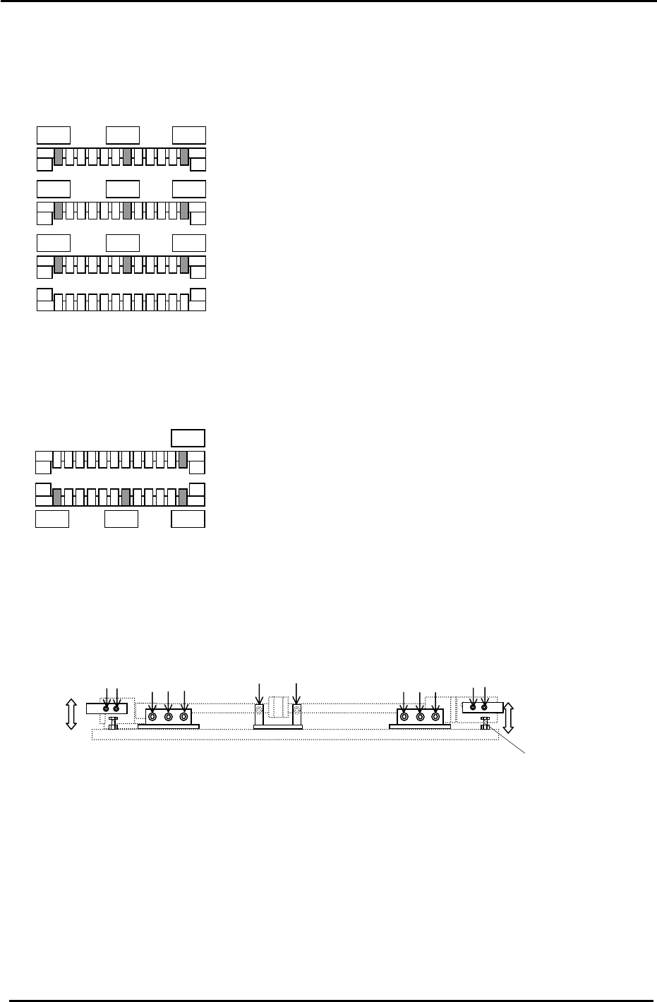
6. (Final leveling check) The reference point for measuring the table flatness is the far right claw on
the adjustable rail, when it is 50mm from the fixed rail (indicated by a 0 in Fig.13). Measure the rail
flatness at the nine points identified in Fig.13.
(Tolerance: +/- 0.15mm,)(within 0.1mm is best)
0
A
d
j
ustable rail at 250mm
A
d
j
ustable rail at 150mm
Ad
j
ustable rail at 50mm
Reference Rail
Figure 13
7. If the adjustable rail is not flat at the locations illustrated, it may be necessary to repeat step 5.
8. Once the adjustable rail flatness is within tolerance. Use the 0 position (Fig.14) as the reference to
check the height between the adjustable and reference rails at the hi-lighted positions.
0
Ad
j
ustable rail at 50mm
Reference Rail
Figure 14
9. If the height of the reference rail is more than +/-0.1mm than that of the adjustable rail, (or the
reference rail itself is uneven) adjust the reference rail height (flatness), by loosening the bolts
indicated in Fig. 15 and adjust, using the bolts under both sides of the reference rail.
12 Securing bolts
4mm
Bolts
3mm bolts
(CP-742/743(M)E)
4mm
Bolts
3mm
bolts (CP-742/743(M)E)
4mm
Bolts
Adjustment bolt
Figure 15
Fuji Machine Mfg. Co., Ltd. (Okazaki)
SMT Equipment Quality Assurance Dept.
CS Section
3-13