CP7 training(6.0) (1).pdf - 第40页
FK-9F98-27 CP-7 Series T raini ng T ext for Service Engineers Edition 6.0 Chapter 3. X, Y , Z and D-axes Adjustm ent [26/36] (Part 2) – Interference Prevention Sensor Adjustment (CP-742/743(M)E) D1 Pallet 1.5mm Figure 35…
FK-9F98-27 CP-7 Series Training Text for Service Engineers
Edition 6.0 Chapter 3. X, Y, Z and D-axes Adjustment [25/36]
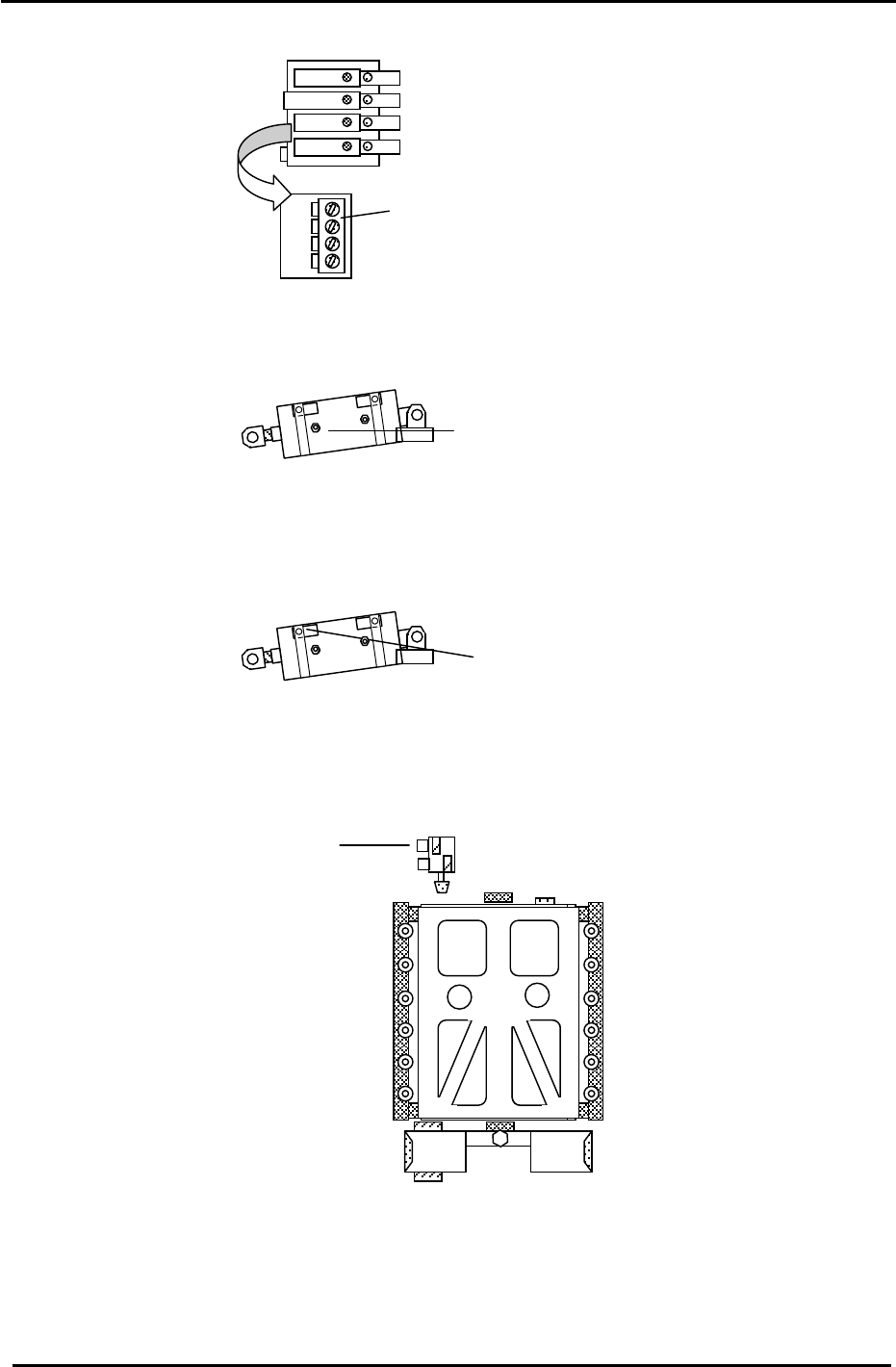
3. Set the 4 PCU Unit Clamp and Unclamp flow controls, 5 x from fully closed then lock.
(A) PCU flow controls
Pallet Up/Down control
PCU Clamper L
PCU Clam
p
er R
Figure 31
Table Stopper Cylinder control
4. Set the D cam cylinder cushioning adjustment screws, 2 x from fully closed, then lock.
Cylinder cushion
adjustment screws.
Figure 32
5. Set the D cam cylinder Upper and Lower Limit Check sensors 0.5mm toward the ON position.
Cylinder check sensors
Figure 33
6. Set the D table notch stopper flow controls 3 x from fully closed then lock.
Notch stopper flow controls
Figure 34
Fuji Machine Mfg. Co., Ltd. (Okazaki)
SMT Equipment Quality Assurance Dept.
CS Section
3-25
FK-9F98-27 CP-7 Series Training Text for Service Engineers
Edition 6.0 Chapter 3. X, Y, Z and D-axes Adjustment [26/36]
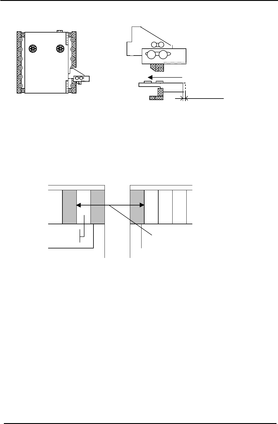
(Part 2) – Interference Prevention Sensor Adjustment (CP-742/743(M)E)
D1 Pallet
1.5mm
Figure 35
1. Check the motion of the interference prevention sensor bracket. Apply grease if necessary
2. Adjust the bracket so that the sensor LED turns ON when pushing the bracket to the left 1.5mm.
3. Check that the pitch between the last feeder slot (D1) and the first feeder slot (D2) is (72mm, CP-
742/743 Series) (59mm, CP-732/733 Series) when the sensor activates. (See the diagram below).
Make sure the bracket does not collide with the mechanical stopper. Use the I/O to check the exact
position where the interference prevention sensor activates: D1(SX041), D2 (SX049)
CP-732/733E Slot (30)
CP-742/743ME “ (40)
CP-742/743E “ (70)
Pallet 2
Slot
(1)
Feeder Pitch
72mm (742/743ME) (742/743E)
59mm (732/733E)
Pallet 1
Figure 36
4. Carry out the following procedure to set the software travel limits for D1 and D2. (CP-742/743(M)E)
4.1 Move D2 to the escape position. (0 pulses)
4.2 Push D1 towards D2 until the interference sensor just turns ON (D1: SX041) and record the
pulse count for D1.
4.3 Move D1, 500 pulses away from the sensor ON position and set the Calibration Data as
follows:
Press: [Maintenance] → [Calibration] → [Travel Limits] → [Minimum Limit D1]
4.4 Move D1 to the escape position (0 pulses)
4.5 Push D2 towards D1 until the interference sensor just turns ON (D2: SX049) and record the
pulse count for D2.
4.6 Move D2, 500 pulses away from the sensor ON position and set the travel Calibration Data
as follows:
Press: [Maintenance] → [Calibration] → [Travel Limits] → [Maximum Limit D2]
Fuji Machine Mfg. Co., Ltd. (Okazaki)
SMT Equipment Quality Assurance Dept.
CS Section
3-26
FK-9F98-27 CP-7 Series Training Text for Service Engineers
Edition 6.0 Chapter 3. X, Y, Z and D-axes Adjustment [27/36]
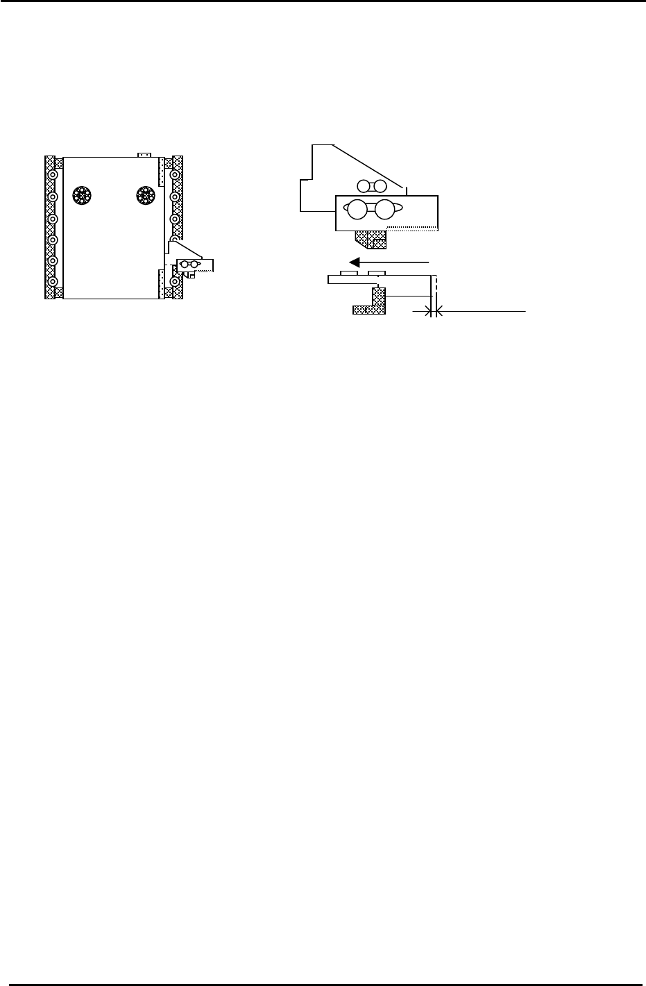
Interference Prevention Sensor Adjustment (CP-732/733E)
1. Check the motion of the interference prevention sensor bracket. Apply grease if necessary.
2. Adjust the bracket so that the sensor LED turns ON when pushing the bracket to the left 1.5mm.
Figure 37
1.5mm
D1 Pallet
3. Set D2 at the escape position. (0 pulses) Move D1 to the minus mechanical stopper and record the
D1 pulse count. (The interference prevention sensor should be ON.) (D1:X041)
4. Move D1 back until the interference prevention sensor just turns OFF. The sensor should turn OFF
1000 +/-500 pulses from the minus mechanical stopper.
5. Move D1, 500 pulses away from the sensor ON position and set the Calibration Data as follows:
Press: [Maintenance] → [Calibration] → [Travel Limits] → [Minimum Limit D1]
6. Set D1 at the escape position. (0 pulses) Move D2 to the plus mechanical stopper and record the D2
pulse count. (The interference prevention sensor should be ON.) (D2:X049)
7. Move D2 back until the interference sensor just turns OFF. The sensor should turn OFF
1000 +/-500 pulses from the plus mechanical stopper.
8. Move D2, 500 pulses away from the sensor ON position and set the Calibration Data as follows:
Press: [Maintenance] → [Calibration] → [Travel Limits] → [Maximum Limit D2]
Fuji Machine Mfg. Co., Ltd. (Okazaki)
SMT Equipment Quality Assurance Dept.
CS Section
3-27