CP7 training(6.0) (1).pdf - 第14页
FK-9F98-27 CP-7 Series T raini ng T ext for Service Engineers Edition 6.0 Chapter 2. Cam Box Adjustm ent [7/8] 2.11 Cam Calibration Dat a Setting (0.03deg/pulse) Since zero setting is not required on the CP-7 Serie s mac…
FK-9F98-27 CP-7 Series Training Text for Service Engineers
Edition 6.0 Chapter 2. Cam Box Adjustment [6/8]
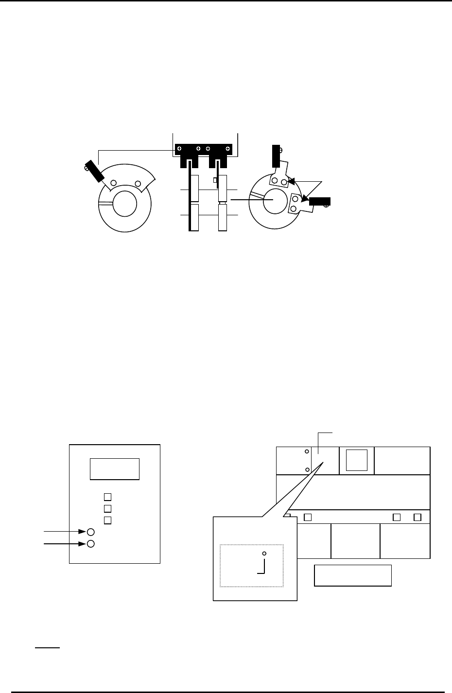
2.10 Image Acquisition Timing Flag Adjustment
1. Adjust the two sensor flags “A” in fig 12, so that the two sensor LED’s turn ON when
rotating the Cam forward to 197 degrees. (Tolerance: 197 ± 1 degree)
2. Adjust flag “B” so the sensor lamp turns ON when rotating the Cam angle forward to 340
degrees. (Tolerance: 340 ± 1 degree). Ensure the LED remains ON for the duration of
time the flag is within the sensor.
Part height trigger sensor * 2
“A”
Dust check trigger sensor *3
“B”
Vision system trigger sensor *1
Figure 12
3. The three sensors mentioned above serve the following purposes.
a. The vision system trigger sensor informs the VP card to take the component image
at 197 degrees. (station 5)
b. The part height trigger sensor informs the part height unit to take the component
thickness (nozzle length) image at 197 degrees. (station 6)
c. The dust check trigger sensor informs the part height unit when to check the
windows for dust etc. (checks from 110 to 340 degrees). (station 6)
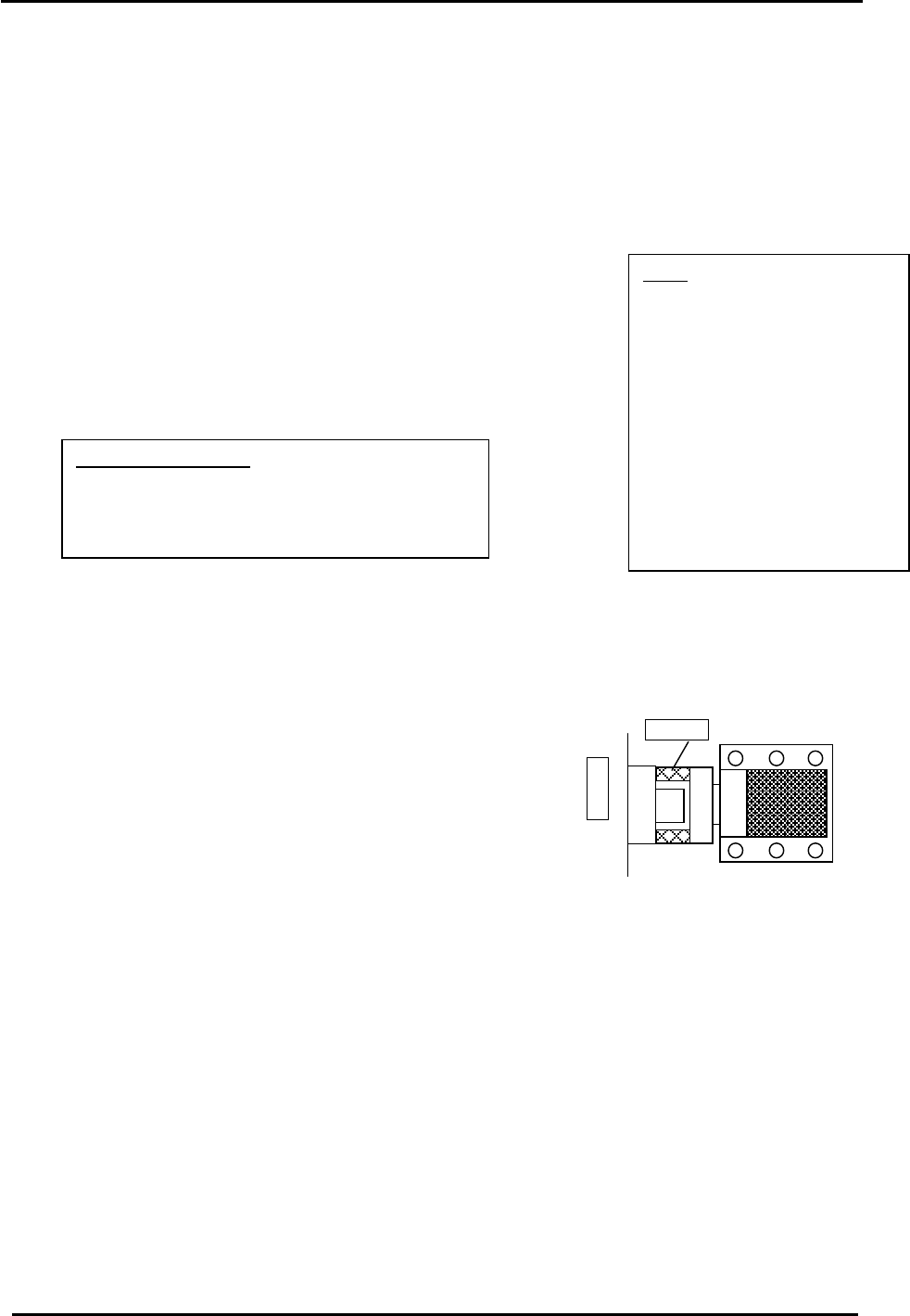
Note: The three sensors mentioned above are NOT connected to the I/O. To monitor the
sensor operating conditions, check the LED’s at the following locations:
PCB No.
AEEPE7002
Machine Rear
10LED 1
* 1
1.03
Dust Sensor
Measurement
Sensor
* 3
* 2
Upper left enclosure
Figure 13
Figure 14
Note: In order to monitor the dust sensor signal, go to the I/O and temporarily turn Y042
OFF. Normally, this function is automatically controlled by the system software.
Fuji Machine Mfg. Co., Ltd. (Okazaki)
SMT Equipment Quality Assurance Dept.
CS Section
2-6

FK-9F98-27 CP-7 Series Training Text for Service Engineers
Edition 6.0 Chapter 2. Cam Box Adjustment [7/8]
2.11 Cam Calibration Data Setting (0.03deg/pulse)
Since zero setting is not required on the CP-7 Series machines, (absolute encoder system
employed) a reference position called, “Origin Position Offset” is needed for tracking the cam
motor position. Follow the procedure below in order to set the origin position offset for the
cam motor under the following two conditions.
When the Cam Motor coupling has already been tightened:
1. With the machine power ON, press the Servo count tab at the bottom of the screen to display
the servo pulse counts.
2. Turn the cam (using the cam handle) until the Cam pulse counts are within 0 +/– 6000 and set
the cam angle to 0 degrees.
3. With the cam at 0 degrees and the pulse counts within the specified range, set this position
into calibration data as follows:
Press: [Maintenance] → [Calibration] → [Origin Pos Offset] → [CAM]
When the Cam Motor coupling has been released.
1. With the machine power ON, press the Servo count tab at the bottom of the screen to display
the servo pulse counts.
2. Ensure the cam is set at 0 degrees.
3. Rotate the cam motor shaft until the Cam pulse counts are within 0 +/– 6000.
4. With the cam at 0 degrees and the pulse counts within the specified range, tighten the
coupling to 33N.m
5. With the cam at 0 degrees and the pulse counts within the specified range, set this position
into calibration data as follows:
Press: [Maintenance] → [Calibration] → [Origin Pos Offset] → [CAM]
Fuji Machine Mfg. Co., Ltd. (Okazaki)
SMT Equipment Quality Assurance Dept.
CS Section
2-7
FK-9F98-27 CP-7 Series Training Text for Service Engineers
Edition 6.0 Chapter 3. X, Y, Z and D-axes Adjustment [1/36]
CHAPTER 3 X, Y, Z and D-axis Adjustment
3.1 Interference Check
1. Confirm that the X and Y couplings are loosened and check for any interference by moving the
axes through their full movement range manually.
2. Check that the sensors and sensor flags do not collide.
3. Check that the two D-axis pallet up and down cylinders are locked at their lower limit by I/O.
(Y056 D1) (Y067 D2)
Note:
When the coupling is loose
and the servo ON, vibration
may occur. It is best to lower
the gain level to 1/10 the
original value when carrying
out adjustments. When
completed, remember to
return the gain level to the
original value. Check servo
pack gain parameter: PN100
4. Check that the D-axis stoppers are retracted.
(Y059 D1) (Y069 D2)
3.2 X Axis Adjustment and Calibration Data Setting
Equipment Checklist:
1- 14 N.M torque wrench with 5mm attachment
1- Small size 5mm L-wrench with pipe
1- Small mirror
1- 3mm
T
-wrench
3.2.1 CP-742/743(M)E X-axis Adjustment and Calibration Data Setting
1. Remove the minus OT sensor flag (right side) and check that the coupling is loose.
2. Set the X axis pulse count to 2500.
3. Push the X-axis against the + mechanical stopper.
(right stopper facing machine) Fig.1.
4. Temporarily half lock the coupling with a 5mm wrench and pipe.
X-table
Stopper
Counter Value: 2500 pulses
5. Move the XY table away from the + mechanical stopper.
6. Lock the coupling with a 14N.m torque wrench.
Figure 1
7. Return the XY table to the + mechanical stopper and record the pulse count at this position. It
must be 2500 +/- 100 pulses.
8. Check the alignment of the OT sensor flags and OT sensors.
9. Set the – OT sensor so that it turns ON 2000 pulses back from the + mechanical stopper. It
must be 500 +/- 100 pulses.
10. Move the X-axis back 500 pulses from where the – OT sensor turns ON and set the Calibration
Data value. (Max Limit Position)
Press: [Maintenance] → [Calibration] → [Travel Limits] → [Maximum Limit X]
11. Move the XY table to the – mechanical stopper and record the pulse count at this position. It
must be – 278000 +/- 1000 pulses.
Fuji Machine Mfg. Co., Ltd. (Okazaki)
SMT Equipment Quality Assurance Dept.
CS Section
3-1