CP7 training(6.0) (1).pdf - 第19页
FK-9F98-27 CP-7 Series T raini ng T ext for Service Engineers Edition 6.0 Chapter 3. X, Y , Z and D-axes Adjustm ent [5/36] 3.3 Y - Axis Adjustment and Calibration Dat a Setting Equipment Checklist : 1- 8 N.m torque wren…

FK-9F98-27 CP-7 Series Training Text for Service Engineers
Edition 6.0 Chapter 3. X, Y, Z and D-axes Adjustment [4/36]
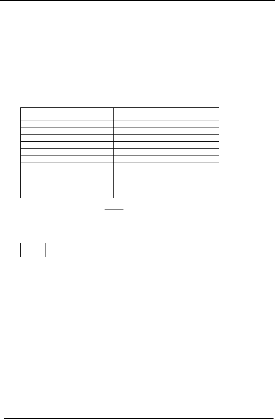
11. Table 2 lists the X axis Calibration Data and physical data reference values:
CP-732/733E
X Axis Calibration Data Item
Reference Value (0.002mm/pulse)
+ Mechanical stopper 2500 +/- 100
– OT sensor 500 +/- 100
Max Limit Position X (– OT – 500) 0 +/-100
PCB Check Position X (left to right m/c) – 190000
Loading Position XL IN – 220500
Loading Position XL OUT – 11250
Mark Read Position XC (left to right m/c) – 180500
Placing Position X0 (left to right m/c) – 222500
Minimum Limit Position X (+ OT + 500) – 225000 +/- 1000
+ OT sensor – 225500 +/- 1000
– Mechanical stopper – 227500 +/- 1000
Table 2
12. Check sensor reaction by I/O
<I/O Æ Servo Æ IN>
SX009 X AXIS +OT (X Plus OT)
SX00A X AXIS –OT (X Minus OT)
Fuji Machine Mfg. Co., Ltd. (Okazaki)
SMT Equipment Quality Assurance Dept.
CS Section
3-4
FK-9F98-27 CP-7 Series Training Text for Service Engineers
Edition 6.0 Chapter 3. X, Y, Z and D-axes Adjustment [5/36]
3.3 Y- Axis Adjustment and Calibration Data Setting
Equipment Checklist:
1- 8 N.m torque wrench with 4mm attachment
1- Y-axis spacing jig (Jig. No.:DGPJ0161)
1- 3mm T-wrench
1- 4mm L-wrench and pipe
3.3.1 CP-742/743(M)E Y- axis Adjustment and Calibration Data Setting
1. Check that the coupling is loose, then set the Y axis pulse counter at 110000 pulses.
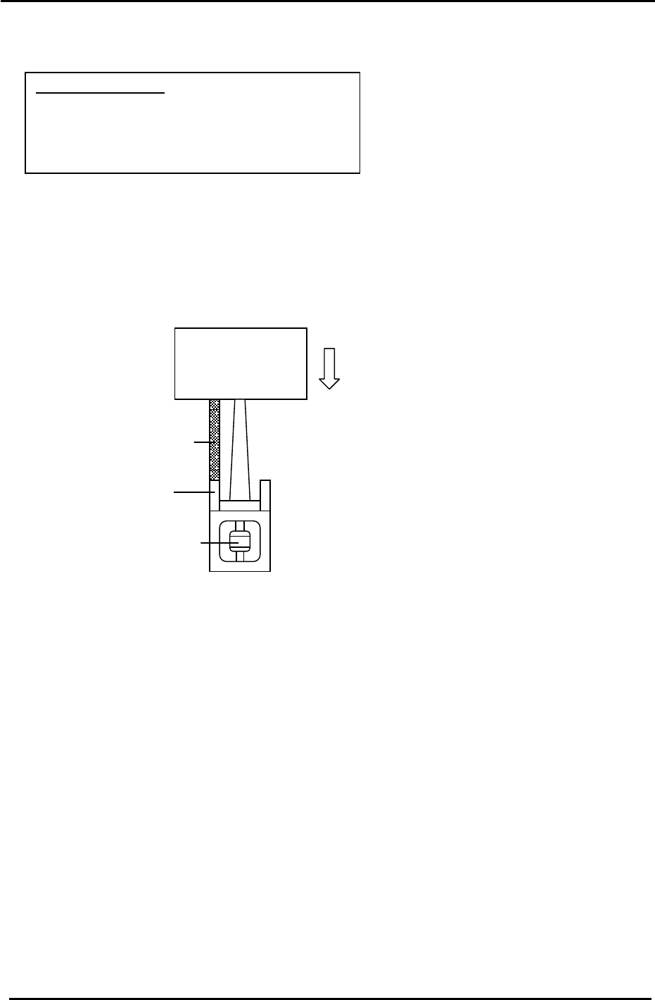
2. Install the Y-axis spacer jig (225mm) (Fig.3) and pull the table against the jig.(Jig No.: DGPJ0161)
Figure 3
Y-axis Table
Y- axis Coupling
Spacing Jig
Stopper
3. Make sure the coupling is in the center of the shaft and temporarily half lock it with a 4mm wrench
and pipe.
4. Remove the jig.
5. Pull the Y-axis to the – mechanical stopper.
6. Record the Y pulse count at the – mechanical stopper. It must be close to –2500. If not, then offset
the value and repeat the steps above.
7. Finally, lock the coupling bolts with a 8N.m torque wrench.
8. Check the alignment of the OT sensor flags and OT sensors.
9. Set the – OT sensor so that it turns ON 2000 pulses away from the – mechanical stopper. It must
be – 500 +/- 100 pulses.
10. Move the Y-axis 500 pulses away from the position where the – OT sensor turns ON and set the
Calibration Data. (Min Limit Position)
Press: [Maintenance] → [Calibration] → [Travel Limits] → [Minimum Limit Y]
Fuji Machine Mfg. Co., Ltd. (Okazaki)
SMT Equipment Quality Assurance Dept.
CS Section
3-5
FK-9F98-27 CP-7 Series Training Text for Service Engineers
Edition 6.0 Chapter 3. X, Y, Z and D-axes Adjustment [6/36]
11. Move the XY table to the + mechanical stopper and record the pulse count at this position. It
must be 241500 +/- 1000 pulses.
12. Set the + OT sensor so that it turns ON 500 pulses back from the + mechanical stopper. It
must be 241000 +/- 1000 pulses.
13. Move the Y-axis back 500 pulses from where the +OT sensor turns ON and set the Calibration
Data value. (Max Limit Position)
Press: [Maintenance] → [Calibration] → [Travel Limits] → [Maximum Limit Y]
14. Table 3 lists the Y-axis Calibration Data and physical data reference values:
CP-742/743(M)E
Y Axis Calibration Data Item
Reference Value (0.002mm/pulse)
– Mechanical stopper – 2500 +/- 100
– OT sensor – 500 +/- 100
Minimum Limit Position Y (– OT + 500) 0 +/- 100
Loading Position YL IN 2500
Loading Position YL OUT 2500
Mark Read Position YC 226000
PCB Check Position Y 205000
Placing Position Y0 238500
Max Limit Position Y (+ OT – 500) 240500 +/- 1000
+ OT sensor 241000 +/- 1000
+ Mechanical stopper 241500 +/-1000
Table 3
15. Check sensor reaction by I/O
<I/O Æ Servo Æ IN>
SX011 Y AXIS +OT (Y plus OT)
SX012 Y AXIS –OT (Y minus OT)
Fuji Machine Mfg. Co., Ltd. (Okazaki)
SMT Equipment Quality Assurance Dept.
CS Section
3-6