CP7 training(6.0) (1).pdf - 第95页
FK-9F98-27 CP-7 Series T raining T ext for Service Engineers Edition 6.0 Chapter 5. Loader and Con veyor Adjustment [27/28] *CP-742/743(M)E Calibration Item No. Ti m e ( m s ) Flow Controls (Ref.) 1.In-Lifter Up/Down 150…
FK-9F98-27 CP-7 Series Training Text for Service Engineers
Edition 6.0 Chapter 5. Loader and Conveyor Adjustment [26/28]
5.26 Loader Cylinder Adjustment
Adjustment of Cylinder Controller
1. Press [Maintenance] Æ [Loader Cylinder Adjustment] to enter the cylinder adjustment command.
2. Select the item number of the cylinder, which is going to be adjusted or calibrated.
3. Press [Times], and enter “10”.
4. Pressing [START] will activate “Waiting for START button”. Press [START] to calibrate.
Results of the 10 movements Max (ms) and Min (ms) will be displayed after the calibration. Adjust
the cylinder controller so that the results are within the appropriate ranges shown below.
* As for the Carrier and XY table open/close time, check the total time for clamping & unclamping.
*CP-732/733E
Calibration Item No.
Time (ms)
Flow Control
Position
1.In-Lifter Up/Down 1500 ± 50
0.5 rev. from
fully closed.
2.In-Carrier Clamper Advanced Limit (Fixed side)
3.In-Carrier Clamper Advanced Limit (Adjustable side)
4.In-Carrier Clamper Retract Limit(Fixed side)
5.In-Carrier Clamper Retract Limit (Adjustable side)
Less than
300
No flow control
6.In-Carrier Return 3000 ± 150 (See Page 5 -28)
7.In-Carrier Loading
Fill in the
measurement
result
8.Main Clamper (Fixed side) Less than 300
6 rev. from
fully closed
9.Out-Lifter Up/Down 1500 ± 50
0.5 rev. from
fully closed.
10.Out-Carrier Clamper Advanced Limit (Fixed side)
11.Out-Carrier Clamper Advanced Limit (Adjustable side)
12.Out-Carrier Clamper Retract Limit (Fixed side)
13.Out-Carrier Clamper Retract Limit (Adjustable side)
Less than
300
No flow control
14.Out-Carrier Return 3000 ± 150 (See Page 5 -28)
15.Out-Carrier Loading
Fill in the
measurement
Result
16.Main Clamper (Adjustable side)
Less than
300
135±10
6 rev. from
fully closed
Fuji Machine Mfg. Co., Ltd. (Okazaki)
SMT Equipment Quality Assurance Dept.
CS Section
5-26
FK-9F98-27 CP-7 Series Training Text for Service Engineers
Edition 6.0 Chapter 5. Loader and Conveyor Adjustment [27/28]
*CP-742/743(M)E
Calibration Item No.
Time (ms)
Flow Controls
(Ref.)
1.In-Lifter Up/Down 1500 ± 50
0.5 rev. from
fully closed.
2.In-Carrier Clamper Advanced Limit (Fixed side)
3.In-Carrier Clamper Advanced Limit (Adjustable side)
4.In-Carrier Clamper Retract Limit(Fixed side)
5.In-Carrier Clamper Retract Limit (Adjustable side)
Less than
280
No flow control
6.In-Carrier Return 3500 ± 150 (See Page 5 -28)
7.In-Carrier Loading
Fill in the
measurement
result
8.Main Clamper (Fixed side)
Less than 280
(135 ± 10)
6 rev. from
fully closed
9.Out-Lifter Up/Down 1500 ± 50
0.5 rev. from
fully closed.
10.Out-Carrier Clamper Advanced Limit (Fixed side)
11.Out-Carrier Clamper Advanced Limit (Adjustable side)
12.Out-Carrier Clamper Retract Limit (Fixed side)
13.Out-Carrier Clamper Retract Limit (Adjustable side)
Less than
280
No flow control
14.Out-Carrier Return 3500 ± 150 (See Page 5 -28)
15.Out-Carrier Loading
Fill in the
measurement
Result
16.Main Clamper (Adjustable side)
Less than
280
135±10
6 rev. from
fully closed
Note: Regarding the adjustment for the main clamper closed time on the reference and movable
sides, adjust the slower main clamper to 135±10.
*When the value is out of tolerance for items without flow controls, check the pneumatic tubing for kinks and
plastic ties which are too tight.
Fuji Machine Mfg. Co., Ltd. (Okazaki)
SMT Equipment Quality Assurance Dept.
CS Section
5-27
FK-9F98-27 CP-7 Series Training Text for Service Engineers
Edition 6.0 Chapter 5. Loader and Conveyor Adjustment [28/28]
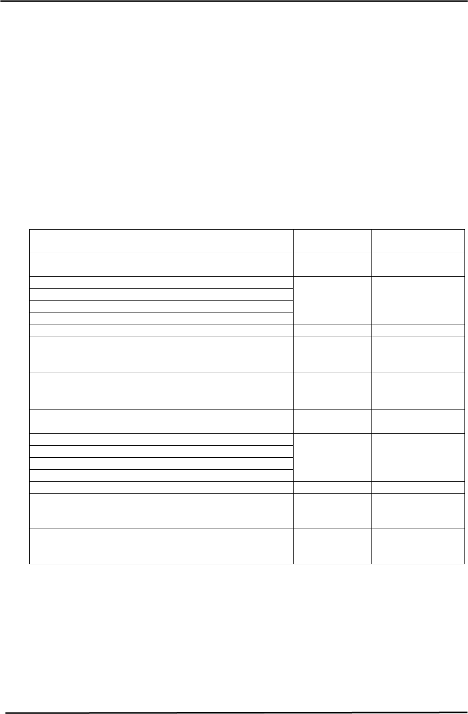
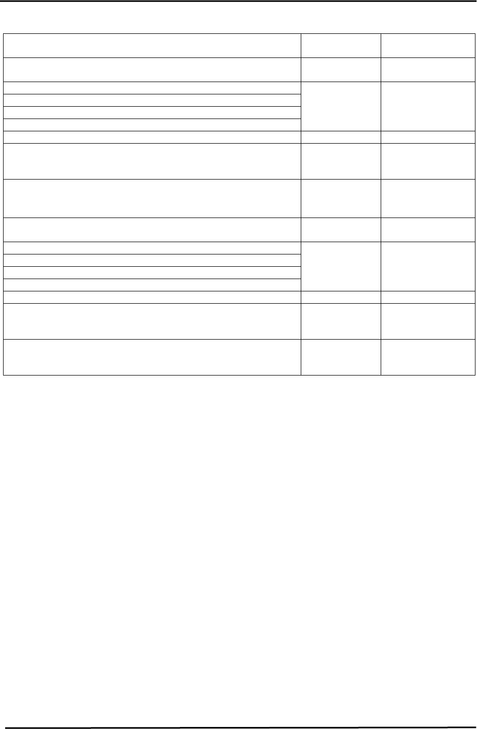
[Adjustment of item “6. IN_C MOVE 14. OUT_C MOVE”]
FWD
OUT-
controller
BWD
IN-
controller
Figure 50
BWD
IN-
controller
FWD
IN-
controller
BWD
OUT-
controller
BWD
OUT-
controller
FWD
OUT-
controller
FWD
IN-
controller
OUT Carrier
(left side front)
IN Carrier
(right side front)
1. Fully open the OUT controller. Adjust the IN side speed controller so that the calibration times reaches
2000 +/- 150 (ms) for CP-732/733E / CP-742/743(M)E)
2. Adjust the OUT controller so that the calibration time reaches 3000 +/- 150(ms) for CP-732/733E and
3500 +/- 150 (ms) for CP-742/743(M)E.
3. Press the E-stop while the carrier is moving forward and backward. Move the carrier again and check if
the moving speed is within the specified time limits.
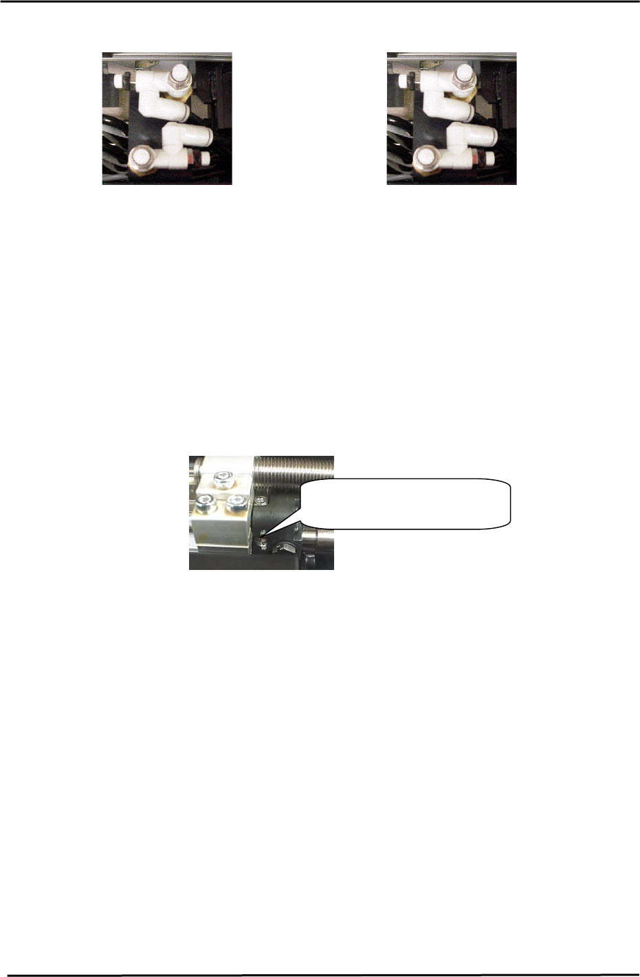
4. To adjust the cushions of the rod-less cylinder, Turn the adjustment screw 3 revolutions away from the
fully closed position.
[Note]: When using Vacuum Back Up Pins, the loading time is calculated as:
[Loading time measurement value] + 0.72.
(A 360ms software timer is used for timing the vacuum ON/OFF cycle.
Rod-less Cylinder (Cushion)
A
d
j
ustment Screw
Figure 51
Fuji Machine Mfg. Co., Ltd. (Okazaki)
SMT Equipment Quality Assurance Dept.
CS Section
5-28