CP7 training(6.0) (1).pdf - 第51页
FK-9F98-27 CP-7 Series T raini ng T ext for Service Engineers Edition 6.0 Chapter 4. S tation Adjustment [2/28] 4.2 PQ, FQ, and RQ S troke Adjustment 1. Adjustment s should be performed with the servo power OFF . 2. Use …
FK-9F98-27 CP-7 Series Training Text for Service Engineers
Edition 6.0 Chapter 4. Station Adjustment [1/28]
Chapter 4 Station Adjustment
4.1 Shaft Assembly Adjustment
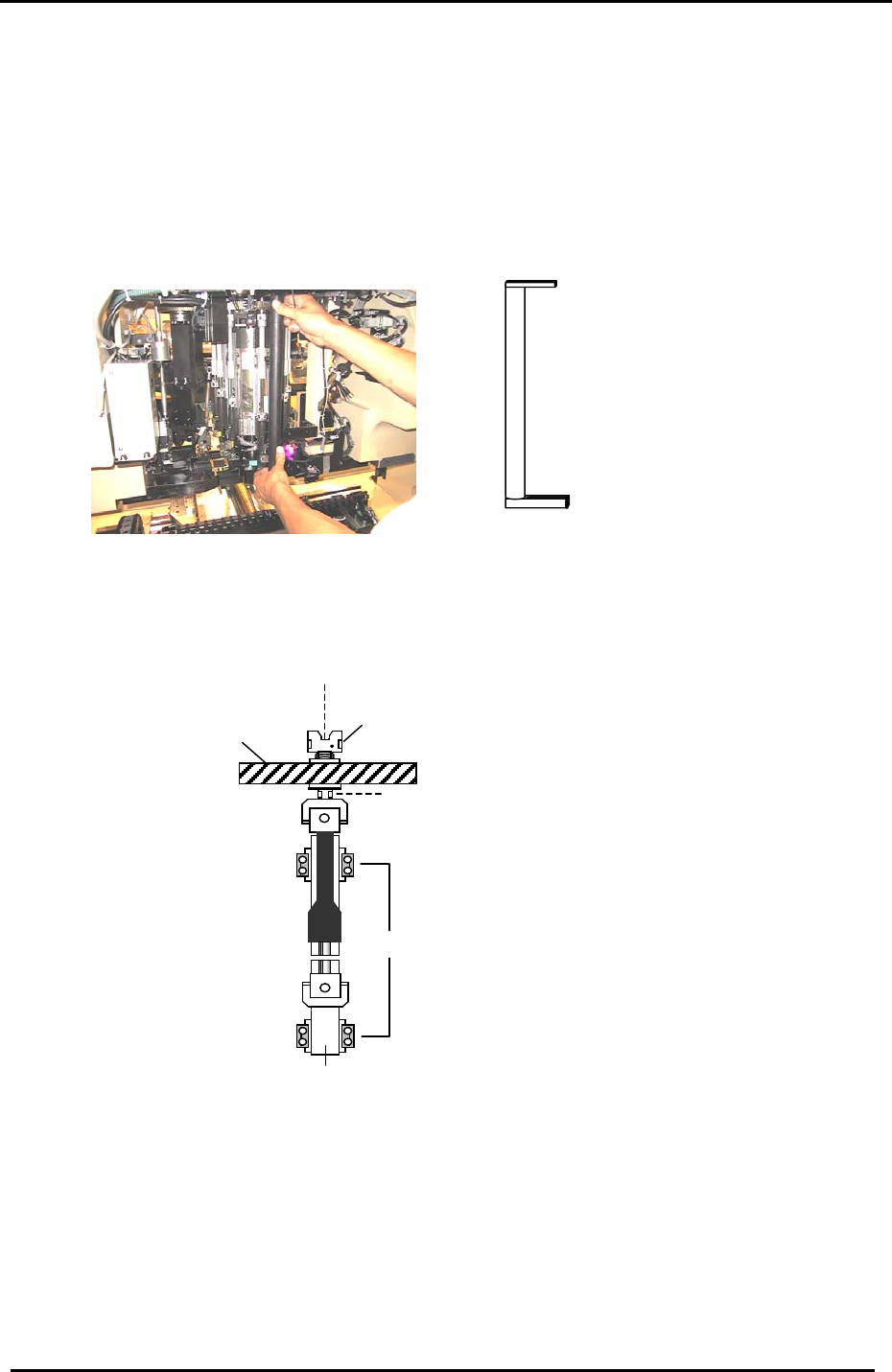
1. With the cam at 0 degrees, turn the 9
th
station placing solenoid valve OFF. (Y034)
2. Make sure that there is a nozzle holder on shaft A.
3. Check the alignment of the holder and clutch at 195 degrees. Use the jig indicated in
Fig.1.
Jig No. CP-732/733E: DCPJ0431
CP-742/743(M)E: DGPJ0020.
Figure 1
4. If the holder and clutch are not aligned correctly, use a 7mm spanner at position A in the
diagram below; and a 2.5mm L-wrench at position B, to loosen the shaft assembly and realign
them.
LM guide block retainers
A
Helical gear
Clutch
Linear guide rail
Figure 2
B
5. When the clutch and holder on the shaft assembly are correctly aligned, there should be no
resistance with the jig.
6. Finally, in preparation for the adjustments that follow, remove the holder from shaft A.
Fuji Machine Mfg. Co., Ltd. (Okazaki)
SMT Equipment Quality Assurance Dept.
CS Section
4-1
FK-9F98-27 CP-7 Series Training Text for Service Engineers
Edition 6.0 Chapter 4. Station Adjustment [2/28]
4.2 PQ, FQ, and RQ Stroke Adjustment
1. Adjustments should be performed with the servo power OFF.
2. Use the low shaft (identified in section 3.16) to set the stroke of stations 2, 8, and 10.
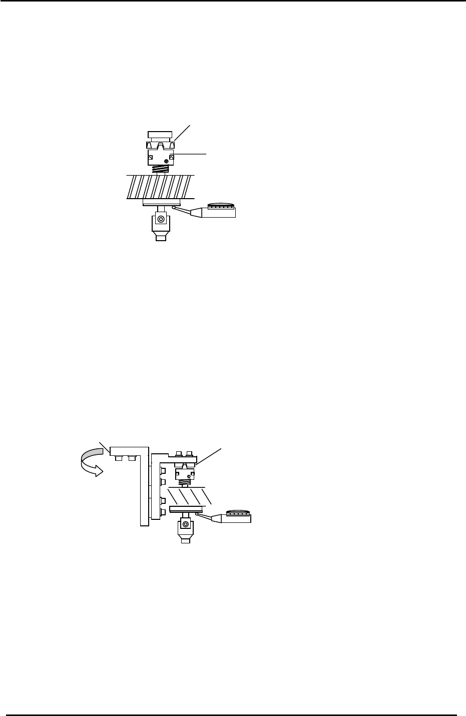
3. With the cam at 200 degrees, clutch (1), and the low shaft clutch (2) should be engaged.
Figure 3
1
2
4. Set the stroke in the range of 0.30 to 0.35mm, (0.31mm is the ideal value). Note that the
stroke value will change when rotating the shaft; set the stroke at the point where the shaft
descends the least. When rotating the shaft, the stroke should not fluctuate by more than
0.05mm.
4.3 3
rd
Station Origin Position and Stroke Adjustment
1. This adjustment should be performed with the servo power OFF.
2. Move the low shaft to the 3
rd
station at 200 degrees.
3. Engage and align the 3
rd
station clutch (1) with the low shaft, by adjusting the position of
bracket (2):
2
1
Figure 4
4. To check that the clutch and low shaft are properly aligned, rotate the shaft, and measure the
difference in stroke when the shaft is at 0, 90, 180, and 270 degrees. Tolerance is 0.030mm.
5. Once the clutch is aligned within tolerance, proceed to set the 3
rd
station stroke.
Fuji Machine Mfg. Co., Ltd. (Okazaki)
SMT Equipment Quality Assurance Dept.
CS Section
4-2
FK-9F98-27 CP-7 Series Training Text for Service Engineers
Edition 6.0 Chapter 4. Station Adjustment [3/28]
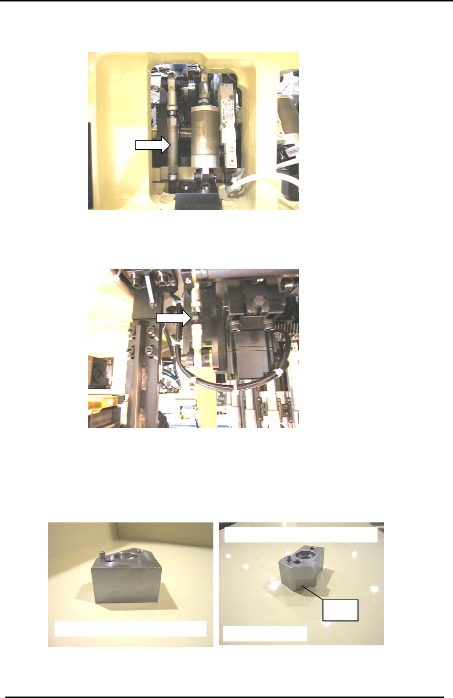
6. Set the length of the third station rod, (located in the cam box at the rear of the machine), to
minimum. (figure 5)
Figure 5
7. With the cam at 200 degrees, set the 3
rd
station stroke within a range of 0.30 to 0.35mm, (0.31mm
is the ideal value). Set the stroke by turning the stroke-adjusting rod, (located at the rear of the
machine next to the PQ motor). (figure 6)
Figure 6
8. When setting the stroke, ensure that the adjustment nut (at the tip of the arrow in fig.6), is in the
center of the stroke-adjusting rod.
9. Once the stroke adjustment is completed, place the 3
rd
station origin jig, or the common jig, on
shaft A.
St 3
Ji
g
No. ADCPJ8232
Common Ji
g
for stations 2, 3, 8 and 10
Station 3 ori
g
in
j
i
g
Ji
g
No. DCPJ0190
Figure 7
Fuji Machine Mfg. Co., Ltd. (Okazaki)
SMT Equipment Quality Assurance Dept.
CS Section
4-3