CP7 training(6.0) (1).pdf - 第42页
FK-9F98-27 CP-7 Series T raini ng T ext for Service Engineers Edition 6.0 Chapter 3. X, Y , Z and D-axes Adjustm ent [28/36] (Part 3) – Pallet Adjustment (CP-742/743(M)E & CP-732/733E ) Note: For details on the ex ac…
FK-9F98-27 CP-7 Series Training Text for Service Engineers
Edition 6.0 Chapter 3. X, Y, Z and D-axes Adjustment [27/36]
Interference Prevention Sensor Adjustment (CP-732/733E)
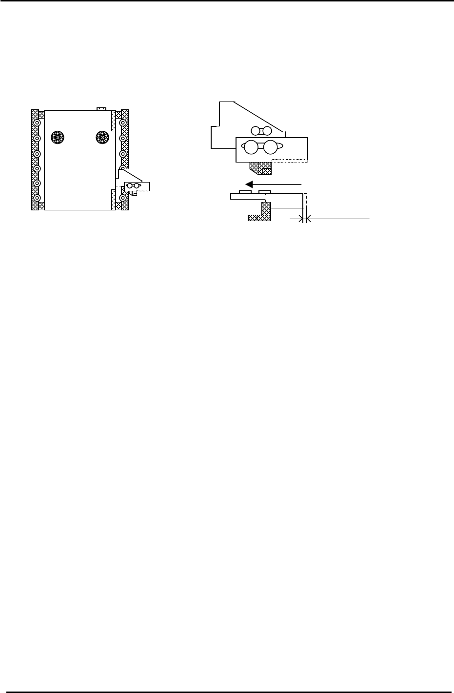
1. Check the motion of the interference prevention sensor bracket. Apply grease if necessary.
2. Adjust the bracket so that the sensor LED turns ON when pushing the bracket to the left 1.5mm.
Figure 37
1.5mm
D1 Pallet
3. Set D2 at the escape position. (0 pulses) Move D1 to the minus mechanical stopper and record the
D1 pulse count. (The interference prevention sensor should be ON.) (D1:X041)
4. Move D1 back until the interference prevention sensor just turns OFF. The sensor should turn OFF
1000 +/-500 pulses from the minus mechanical stopper.
5. Move D1, 500 pulses away from the sensor ON position and set the Calibration Data as follows:
Press: [Maintenance] → [Calibration] → [Travel Limits] → [Minimum Limit D1]
6. Set D1 at the escape position. (0 pulses) Move D2 to the plus mechanical stopper and record the D2
pulse count. (The interference prevention sensor should be ON.) (D2:X049)
7. Move D2 back until the interference sensor just turns OFF. The sensor should turn OFF
1000 +/-500 pulses from the plus mechanical stopper.
8. Move D2, 500 pulses away from the sensor ON position and set the Calibration Data as follows:
Press: [Maintenance] → [Calibration] → [Travel Limits] → [Maximum Limit D2]
Fuji Machine Mfg. Co., Ltd. (Okazaki)
SMT Equipment Quality Assurance Dept.
CS Section
3-27
FK-9F98-27 CP-7 Series Training Text for Service Engineers
Edition 6.0 Chapter 3. X, Y, Z and D-axes Adjustment [28/36]
(Part 3) – Pallet Adjustment (CP-742/743(M)E & CP-732/733E)
Note: For details on the exact location of the sensors described below, please refer to the CP7
series “Mechanical Reference” manual .
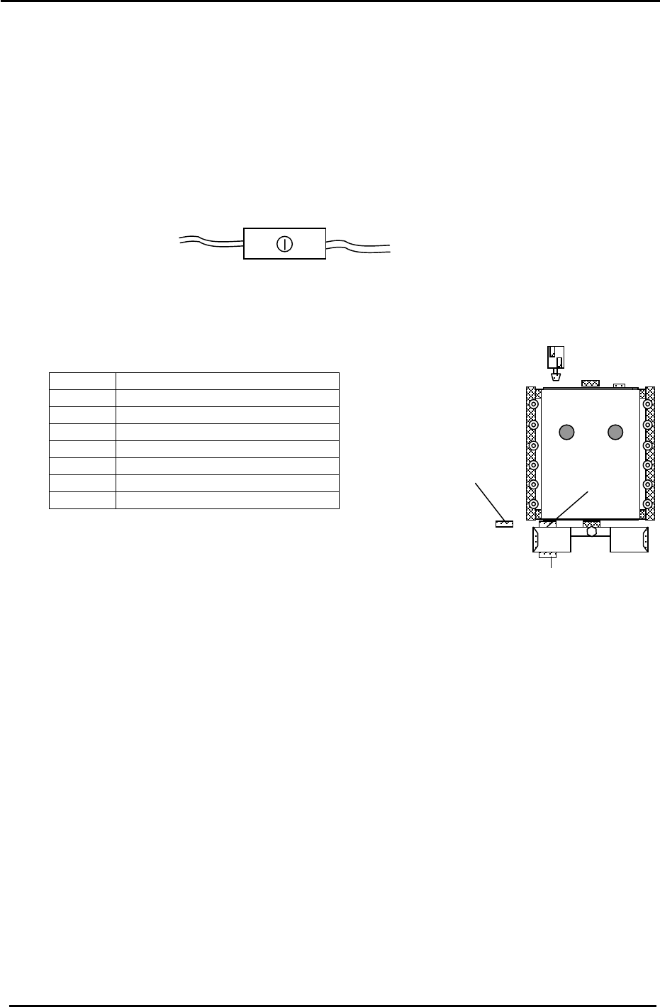
1. Set the height of the PCU Unit, and dock it with the D-axis.
2. Clamp the PCU to the D-axis.
3. Confirm that the PCU SET CHECK sensor is ON. If not, adjust the sensor volume pot so the
sensor turns ON. I/O: D1 (X08B), D2 (X0A1).
4. Set the two PCU CLAMP sensors 2mm toward the position they turn ON.
5. Set the two UNCLAMP sensors 0.5mm toward the position they turn ON.
<I/O → Standard → IN>
(X082) D1 PCU CLAMP CHECK 1
(X083) D1 PCU UNCLAMP CHECK 1
(X084) D1 PCU CLAMP CHECK 2
(X085) D1 PCU UNCLAMP CHECK 2
(X098) D2 PCU CLAMP CHECK 1
(X099) D2 PCU UNCLAMP CHECK 1
(X09A) D2 PCU CLAMP CHECK 2
(X09B) D2 PCU UNCLAMP CHECK 2
6. Unclamp the PCU Unit and disengage it from the D axis.
7. Grease up the lifter mechanism cams with Daphne Eponex #2.
(5) CP-742/743(M)E
sensor
position
(6) (CP-732/733E ONLY)
(5) CP-732/733E
sensor
p
osition
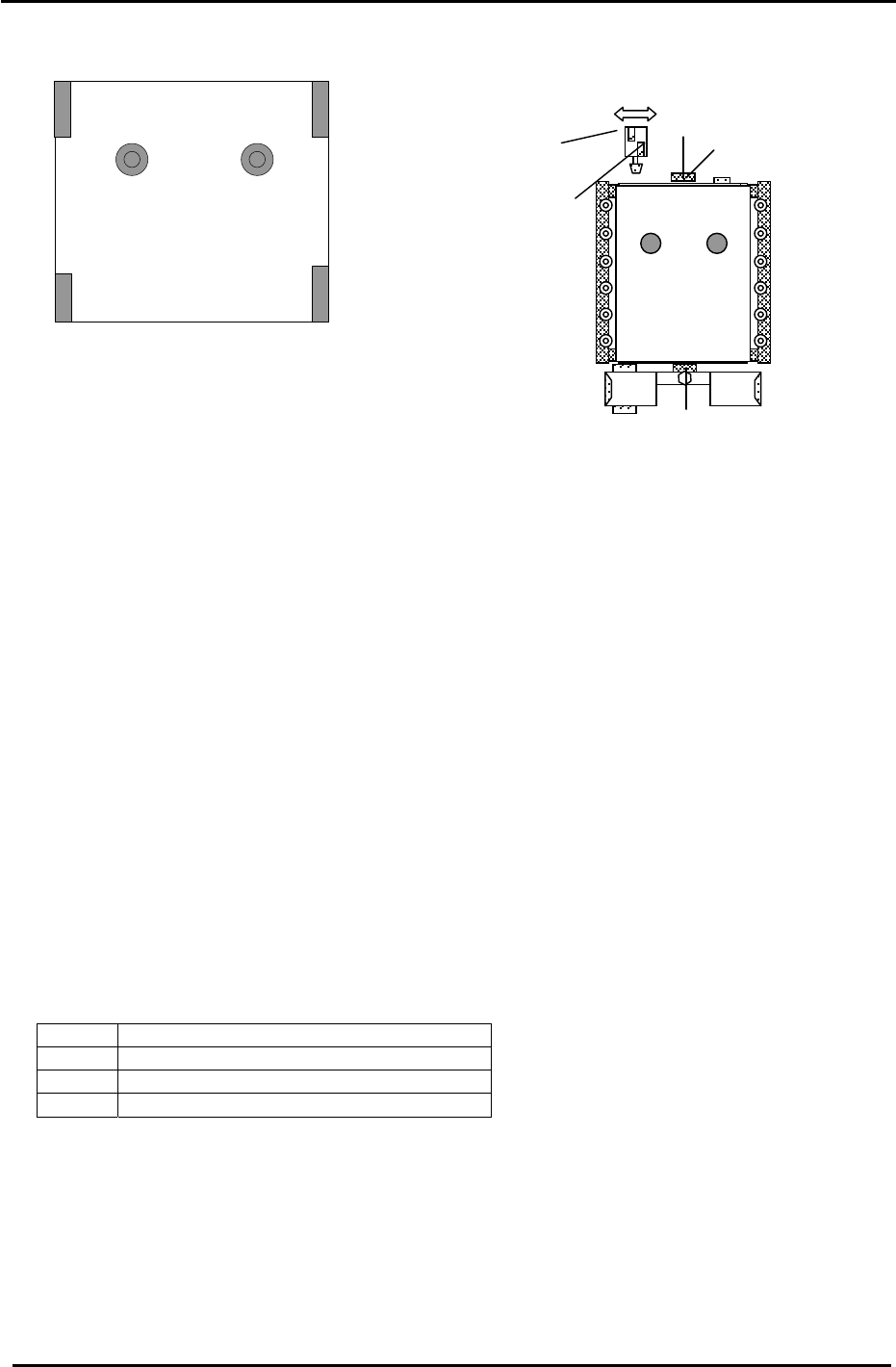
8. Confirm the lifter is at the lower limit.
Figure 38
9. Bring the D-table to 0 pulses; (the D original position)
10. Press the emergency stop button and ensure the servo power is down.
11. At this point, raise the D-table. Check the lifter up and down speed and make slight adjustments
to the flow controls until the motion of the lifter is smooth. (lock the flow controls)
12. With the D table at its upper limit, set the PALLET PASS CHECK (5) sensor volume to half.
I/O: D1 (X08A), D2 (X0A0). (Sensor (6) is only used on CP-732. No adjustment required)
13. From the pallet forward-limit position, retract the pallet 1.0mm and adjust the position of the
pallet pass check sensor so that it turns ON at this point. (volume set at 1.5 scales)
14. Lower and then raise the D-table and confirm that the PALLET PASS CHECK sensor condition
is still okay. (Ensure that it does not turn ON when the pallet is at the forward limit.)
15. With the D-table at the upper limit, clamp the PCU in place.
16. Pull out the pallet and lock it onto the PCU Unit. Then, grease up the bottom section of the D-
table with AFC grease at the hi-lighted areas in Fig.39 on the following page.
Fuji Machine Mfg. Co., Ltd. (Okazaki)
SMT Equipment Quality Assurance Dept.
CS Section
3-28
FK-9F98-27 CP-7 Series Training Text for Service Engineers
Edition 6.0 Chapter 3. X, Y, Z and D-axes Adjustment [29/36]
**Apply AFC grease to the locations hi-lighted (Fig. 39) on the D-table base.
17. Apply Daphne Eponex #2 to the four D-table springs.
1 2
3 4
(1) lower sensor
(3) upper sensor
(4) notch stopper
bracket
(5) stopper sensors
Figure 39
(2)
Figure 40
18. Replace the pallet.
19. Adjust the pallet sensors (1 at upper limit, 2 at lower limit) mounting bracket in the forward/back
directions until the gap between the sensor and dog surface is 1mm.
20. Place two 0.6mm spacers at positions 1 and 2 shown in fig. 39. (CP732/733 ONLY)
21. Lower the table.
22. Set the front side PALLET SETTING CHECK (2) sensor so that it turns OFF with the 0.6mm
spacers in place and ON with 0.4mm spacers in place. I/0: D1 (X088), D2 (X09E) (CP732/733
ONLY)
23. Place 0.6mm spacers at positions 3 and 4 shown in fig. 39, then set the back PALLET SETTING
CHECK (1) sensor so that it turns OFF with the 0.6mm spacers in place and ON with 0.4mm
spacers in place. I/O: D1 (X087), D2 (X09D).
24. Remember to check the PALLET ARRIVE CHECK sensor (3). Check that it is ON when the D-
table is at the upper limit. I/O: D1 (X086), D2 (X09C)
25. For the D-axis notch stopper adjustment (4), Make sure the D pulse count is zero pulses. Move the
stopper bracket so the piston aligns with the center of the notch in the D- table.
26. Set the TABLE STOPPER LOCK CHECK and UNLOCK CHECK sensors (5) 0.5mm toward the
position they turn ON.
<I/O → Standard → IN>
X080 D1 TABLE STOPPER LOCK CHECK
X081 D1 TABLE STOPPER UNLOCK CHECK
X096 D2 TABLE STOPPER LOCK CHECK
X097 D2 TABLE STOPPER UNLOCK CHECK
Fuji Machine Mfg. Co., Ltd. (Okazaki)
SMT Equipment Quality Assurance Dept.
CS Section
3-29