CP7 training(6.0) (1).pdf - 第111页
FK-9F98-27 CP-7 Series Traini ng Text for Service Engineers Edition 6.0 Chapter 7. Cam era Adjustment [5 / 16] The nozzle should be aligned with the cross Figure 6 6. T o align the Wide Camera nozzle image to the crossha…
FK-9F98-27 CP-7 Series Training Text for Service Engineers
Edition 6.0 Chapter 7. Camera Adjustment [4/16]
7.4 Temporary Gain Adjustment
1. Temporarily adjust the camera gain (using the manual gain adjustment trimmer on top of the camera
body) if the nozzle image appears too dark on the monitor.
Top View
of camera
A
F M
SIGNAL
1N
1 l
Manual Gain Adj. Trimmer
GAIN
Figure 4A
7.5 Camera Centering
1. Move a straight 0.7mm nozzle to the 5
th
station and set at 200 degrees.
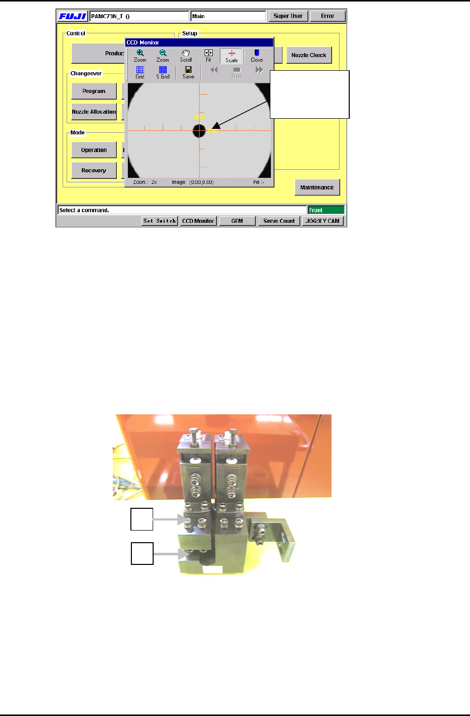
2. View the raw image of the nozzle as follows:
[Press the CCD Monitor tab at the bottom of the screen] → [Select the Wide or Narrow camera]
3. The CCD monitor will appear on the screen. Press [SCALE] to display the crosshairs.
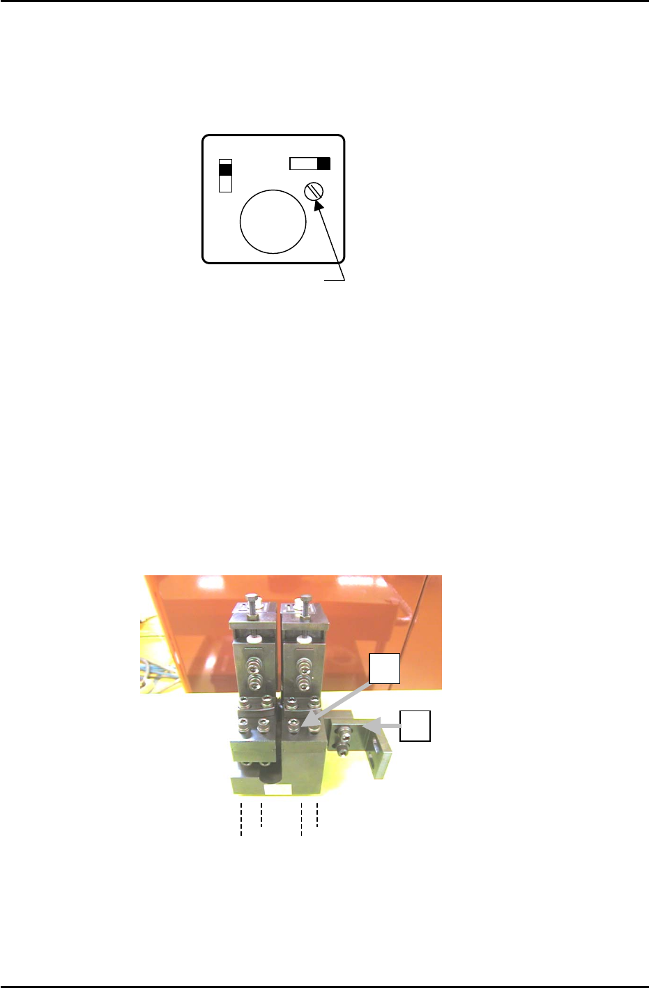
4. Remove the mounting bracket (item 2 in figure 5) securing the camera assembly to the right hand
inner side of the cam box. It will not be possible to perform camera adjustments without removing
this bracket.
Figure 5
2
1
Wide Camera Y-axis
positioning bolts
5. To align the Wide Camera nozzle image to the crosshairs in the Y-direction, loosen the four bolts on
the underside of the camera assembly and adjust the position of the assembly accordingly (see
figure 6). Once the adjustment is complete tighten the bolts with the required amount of torque
(13N.m).
Fuji Machine Mfg. Co., Ltd. (Okazaki)
SMT Equipment Quality Assurance Dept.
CS Section
7-4
FK-9F98-27 CP-7 Series Training Text for Service Engineers
Edition 6.0 Chapter 7. Camera Adjustment [5/16]
The nozzle
should be aligned
with the cross
Figure 6
6. To align the Wide Camera nozzle image to the crosshairs in the X-direction, loosen the X-axis
positioning bolts (Item 1 in figure 5) and adjust the position of the camera accordingly. Once the
adjustment is complete tighten the bolts with the required amount of torque (8N.m).
7. As the narrow camera bracket is attached to the wide camera bracket, it is necessary to adjust the
wide camera bracket first when adjusting both cameras. Performing narrow camera adjustments first
will necessitate the adjustment being performed twice.
8. To adjust the narrow camera in the Y-direction, loosen the Y-axis positioning bolts (Item 1 in figure 7)
and adjust the camera position accordingly. Once the adjustment is complete, tighten the bolts with
the required amount of torque (13N.m).
2
Figure 7
1
9. To adjust the narrow camera in the X-direction, loosen the X-axis positioning bolts (Item 2 in figure 7)
and adjust the camera position accordingly. Once the adjustment is complete tighten the bolts with
the required amount of torque (8N.m).
Fuji Machine Mfg. Co., Ltd. (Okazaki)
SMT Equipment Quality Assurance Dept.
CS Section
7-5
FK-9F98-27 CP-7 Series Training Text for Service Engineers
Edition 6.0 Chapter 7. Camera Adjustment [6/16]
7.6 Focus Adjustments
Figure 8
Wide camera inspection jig
A
DCPJ8100
Narrow camera inspection jig
A
DCPJ8110, Sticker: DCPJ0380
1. Before proceeding to set the focus, ensure the cameras (nozzle image) are centered.
2. Place the wide camera inspection jig on head A and bring it to the 5
th
station at 200 degrees.
3. Display the wide camera monitor using the following commands:
[Press the CCD Monitor tab at the bottom of the screen] → [Select the Wide or Narrow camera]
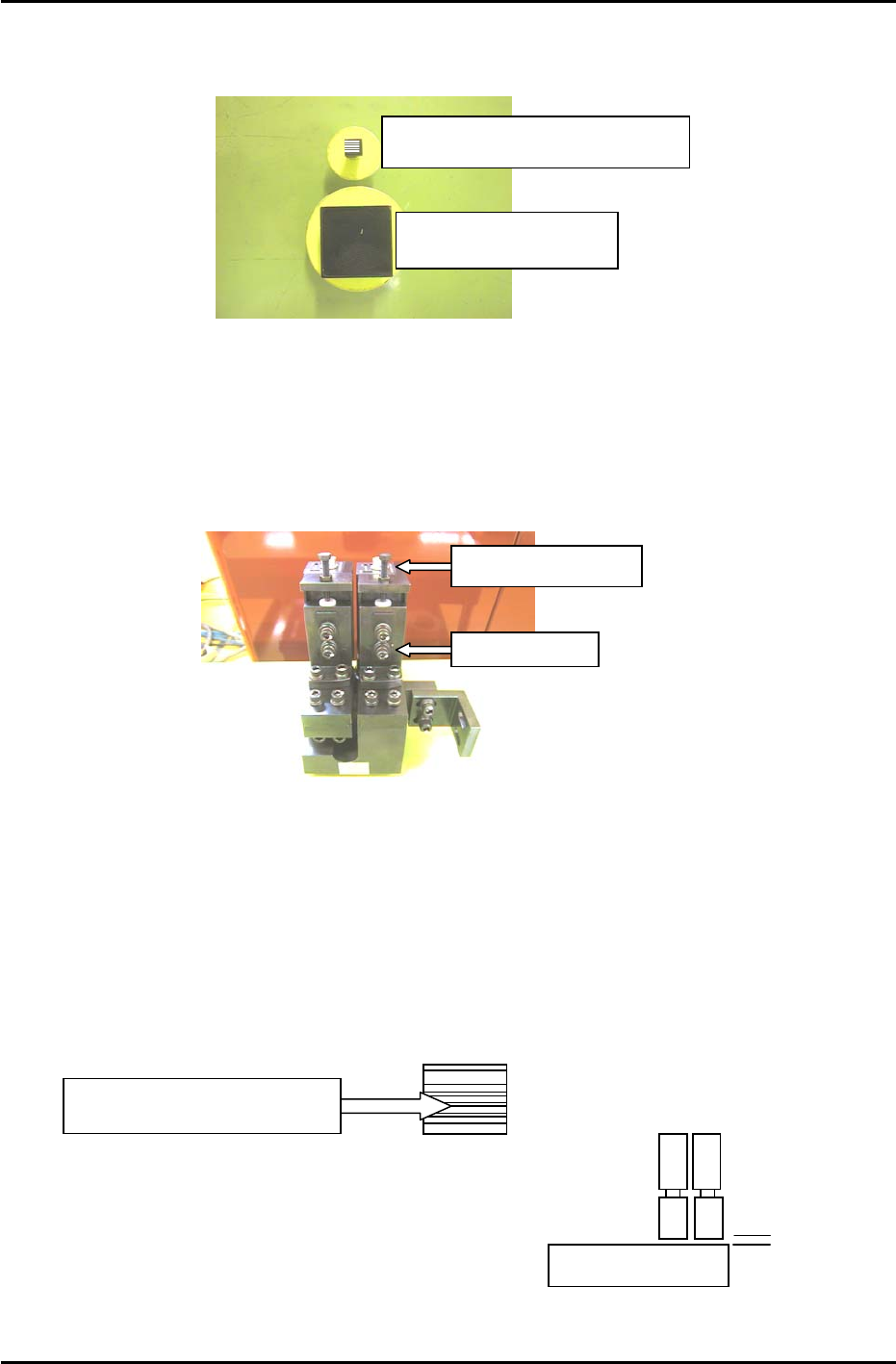
Focus Adjustment Bolt
Securing Bolts
Figure 9
4. Adjust the focus of the wide camera by loosening the two positioning bolts and use the focus
adjustment bolt to raise or lower the camera (see figure 9).
5. The camera is focused when the monitor shows a clear, sharp image of the wide camera inspection
jig.
6. Once the adjustment is complete, tighten the bolts with the required amount of torque (8N.m).
7. Having adjusted the wide camera focus, repeat the procedure for the narrow camera, using the
narrow camera inspection jig. Use the jig with the 0.1,0.2,0.3 lines on the sticker (Jig no.DCPJ8111,
Sticker No.: DCPJ0380) to fine tune the focus using front lighting.
Adjust the camera height
u
n
t
il
a
ll lin
es
a
r
e
in f
ocus
.
8. When both adjustments are finished set the gap
between the lens cover and the prism box to 0.5mm.
0.5mm
Fuji Machine Mfg. Co., Ltd. (Okazaki)
SMT Equipment Quality Assurance Dept.
CS Section
7-6