CP7 training(6.0) (1).pdf - 第113页
FK-9F98-27 CP-7 Series Traini ng Text for Service Engineers Edition 6.0 Chapter 7. Cam era Adjustment [7 / 16] 7.7 Camera Brightness Gain Adjustment 1. Insert a clean 1.3mm nozzle in holde r A, (nozzle position 1) and se…
FK-9F98-27 CP-7 Series Training Text for Service Engineers
Edition 6.0 Chapter 7. Camera Adjustment [6/16]
7.6 Focus Adjustments
Figure 8
Wide camera inspection jig
A
DCPJ8100
Narrow camera inspection jig
A
DCPJ8110, Sticker: DCPJ0380
1. Before proceeding to set the focus, ensure the cameras (nozzle image) are centered.
2. Place the wide camera inspection jig on head A and bring it to the 5
th
station at 200 degrees.
3. Display the wide camera monitor using the following commands:
[Press the CCD Monitor tab at the bottom of the screen] → [Select the Wide or Narrow camera]
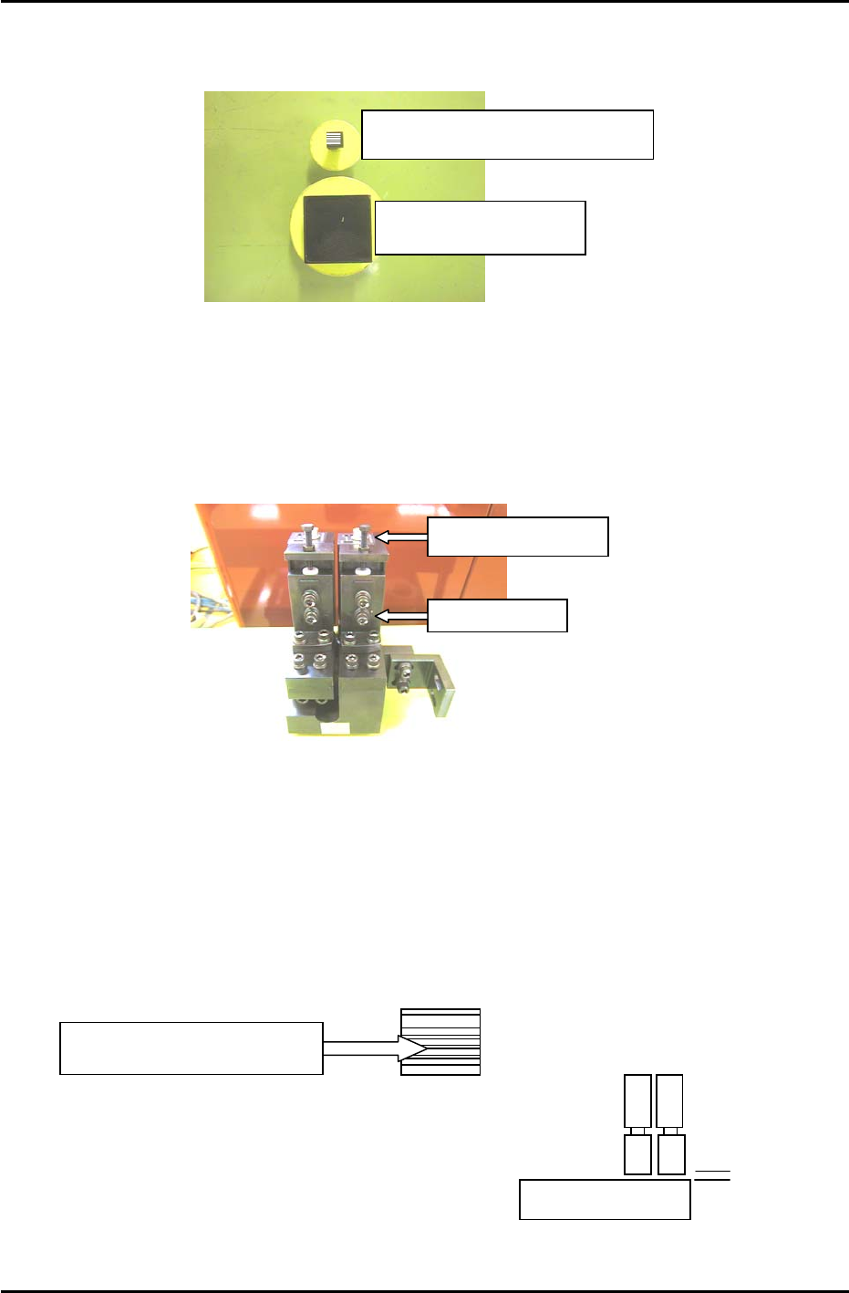
Focus Adjustment Bolt
Securing Bolts
Figure 9
4. Adjust the focus of the wide camera by loosening the two positioning bolts and use the focus
adjustment bolt to raise or lower the camera (see figure 9).
5. The camera is focused when the monitor shows a clear, sharp image of the wide camera inspection
jig.
6. Once the adjustment is complete, tighten the bolts with the required amount of torque (8N.m).
7. Having adjusted the wide camera focus, repeat the procedure for the narrow camera, using the
narrow camera inspection jig. Use the jig with the 0.1,0.2,0.3 lines on the sticker (Jig no.DCPJ8111,
Sticker No.: DCPJ0380) to fine tune the focus using front lighting.
Adjust the camera height
u
n
t
il
a
ll lin
es
a
r
e
in f
ocus
.
8. When both adjustments are finished set the gap
between the lens cover and the prism box to 0.5mm.
0.5mm
Fuji Machine Mfg. Co., Ltd. (Okazaki)
SMT Equipment Quality Assurance Dept.
CS Section
7-6
FK-9F98-27 CP-7 Series Training Text for Service Engineers
Edition 6.0 Chapter 7. Camera Adjustment [7/16]
7.7 Camera Brightness Gain Adjustment
1. Insert a clean 1.3mm nozzle in holder A, (nozzle position 1) and set the holder at station 9.5 at 0
degrees. Ensure the reflective sticker is properly flattened down.
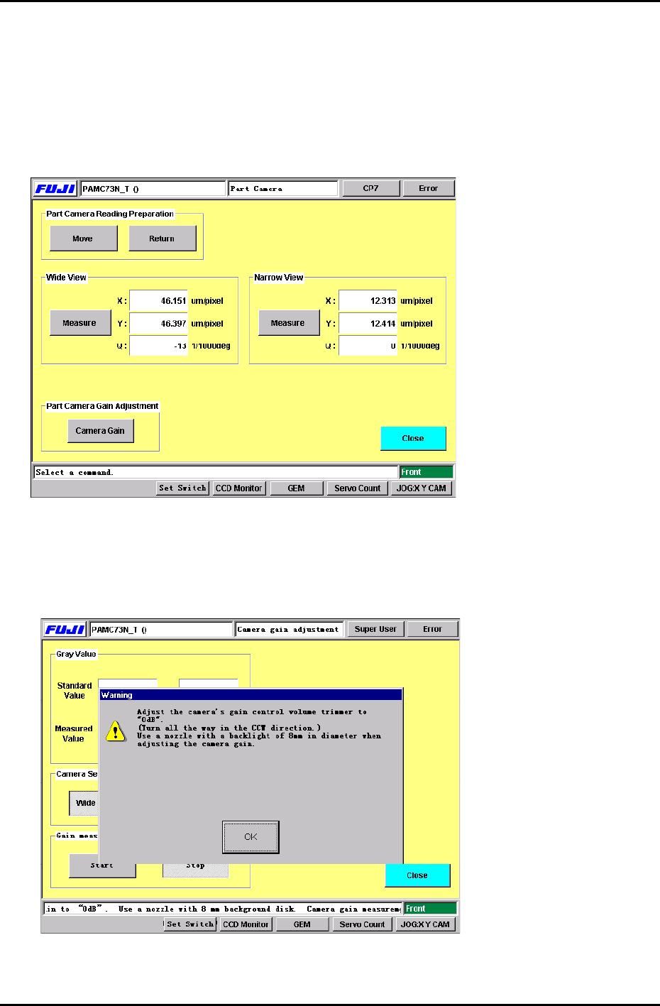
2. Press: [Maintenance] → [Calibration] → [Parts Camera Resolution] to display the Part Camera Gain
Adjustment command. (Figure 10)
FIGURE 10
3. Press: [Move] → [Start] to bring the nozzle into station 5 at 200 degrees. When the nozzle reaches
station 5, press the E-Stop to prevent accidental injury while making the adjustment.
4. Press the Camera Gain button to display Figure 11.
FIGURE 11
5. As shown in Figure 11, a dialog box appears which indicates to turn the camera gain trimmer all the
way in the CCW direction. After doing so, press: [OK].
Fuji Machine Mfg. Co., Ltd. (Okazaki)
SMT Equipment Quality Assurance Dept.
CS Section
7-7
FK-9F98-27 CP-7 Series Training Text for Service Engineers
Edition 6.0 Chapter 7. Camera Adjustment [8/16]
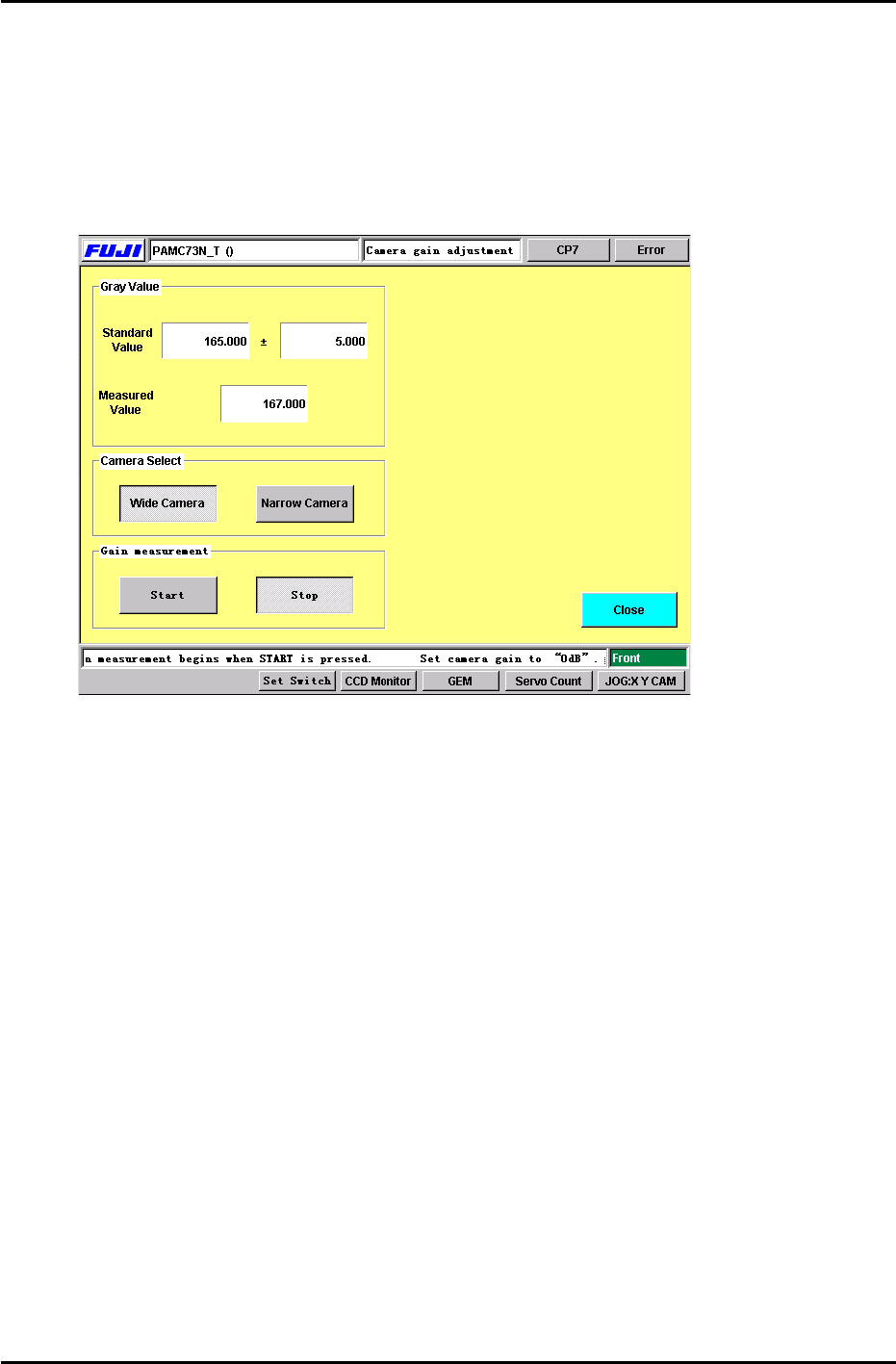
6. Select the camera to be adjusted and press the Start button. Adjust the camera gain trimmer so
the measured value matches the standard value displayed. (+/- 5.00) When completed, press
the stop button. (Figure 12) Carry out the same procedure for both cameras. (Wide and Narrow)
Note: Initially when the start button is pressed, a dialog box will appear briefly indicating not to
adjust the camera trimmer. After this dialog box disappears, it is OK to adjust the camera gain
trimmer.
FIGURE 12
7. Note: The above procedure only needs to be carried out once. However, this adjustment must be
repeated, if the camera gain trimmers are moved.
For further information, check the Fuji web-site for a supplement entittled “CP-7-Series: Adjusting
the Camera Gain”. Document No.: U0121-1.0E.
7.8 Nozzle Check (Temporary measurement)
1. After the camera gain adjustment, it is necessary to perform a nozzle check so the machine can
take a brightness level for the A1 nozzle reflective seal. Primarily, the A1 nozzle brightness
needs to be measured before the resolution can be measured. Otherwise, the vision system will
not be able to see the resolution jig.
Press: [Nozzle Check] → [Nozzle Size] or [Nozzle Bend] → Holder 1 → Enter → Start.
The brightness for the A1 nozzle must be measured in order to carry out the resolution
measurement performed in the next step. It is not necessary to install the other nozzles in
B1 to P1. A1 is the only nozzle position required at this time.
Fuji Machine Mfg. Co., Ltd. (Okazaki)
SMT Equipment Quality Assurance Dept.
CS Section
7-8