CP7 training(6.0) (1).pdf - 第122页
FK-9F98-27 CP-7 Series T raini ng T ext for Service Engineers Edition 6.0 Chapter 8. Placement [2/2] 11. If the data from P AM is within tolerance, use the [Wide] camera and chec k the placement s to ensure they are with…
FK-9F98-27 CP-7 Series Training Text for Service Engineers
Edition 6.0 Chapter 7. Camera Adjustment [15/16]
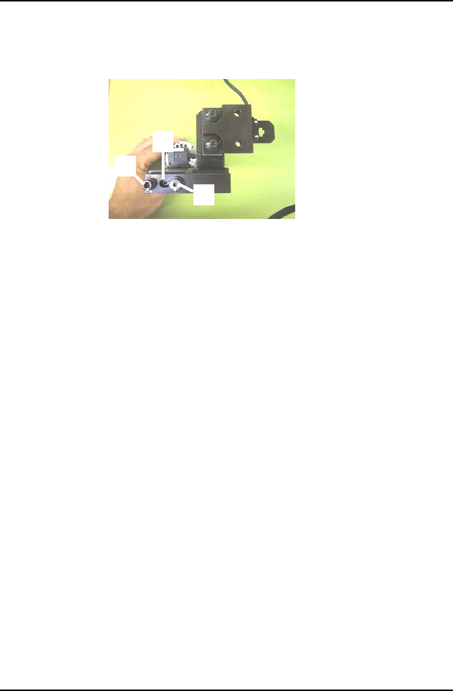
5. To adjust the camera angle, loosen the fixing bolt (item 1 in figure 22) holding the camera in
position. Rotate the 3mm eccentric bolt (item 2 in figure 22) while re-measuring until the value for
Delta Q comes to zero. Tolerance: 0 +/- 50 (1/1000 deg.). There is no need to touch the pivot (Item
3 in figure 22).
6. Once the value for delta Q is within tolerance, tighten the fixing bolt and then confirm that it is still
within tolerance.
7. Receive the new Calibration Data to the host PC.
1
3
2
Figure 22
Fuji Machine Mfg. Co., Ltd. (Okazaki)
SMT Equipment Quality Assurance Dept.
CS Section
7-15

FK-9F98-27 CP-7 Series Training Text for Service Engineers
Edition 6.0 Chapter 8. Placement [2/2]
11. If the data from PAM is within tolerance, use the [Wide] camera and check the placements to
ensure they are within tolerance.
12. Finally, copy the X/Y Placing offset Calibration Data from nozzle No.1 and paste at nozzle positions:
2,3,4,5,6.
PAM Tolerance Values
∆ X ∆Y
≤+/– 15 (1/1000mm)
∆ Q
≤+/– 200 (1/1000Deg.)
3 sig. X/Y
≤ 49 (1/1000mm)
3 sig. Q
≤ 990 (1/1000Deg.)
6 sig. X/Y
≤ 98 (1/1000mm)
6 sig. Q
≤ 1980 (1/1000Deg.)
X/Y Max
≤ +/– 60 (1/1000mm)
X/Y Min
≤ +/– 60 (1/1000mm)
(Minimum allowable CPK value = 1.333)
Note 1: The above figures represent tolerances for new machines. Due to many factors, it
may be difficult to achieve the same results with older equipment.
Note2: When running machine PAM, refer to the PAM Operation Manual in the
“Supplemental Information” at the back of this manual.
Fuji Machine Mfg. Co., Ltd. (Okazaki)
SMT Equipment Quality Assurance Dept.
CS Section
8-2
FK-9F98-27 CP-7 Series Training Text for Service Engineers
Edition 6.0 Chapter 9, Miscellaneous Adjustments [1/6]
Chapter 9 Miscellaneous Adjustments
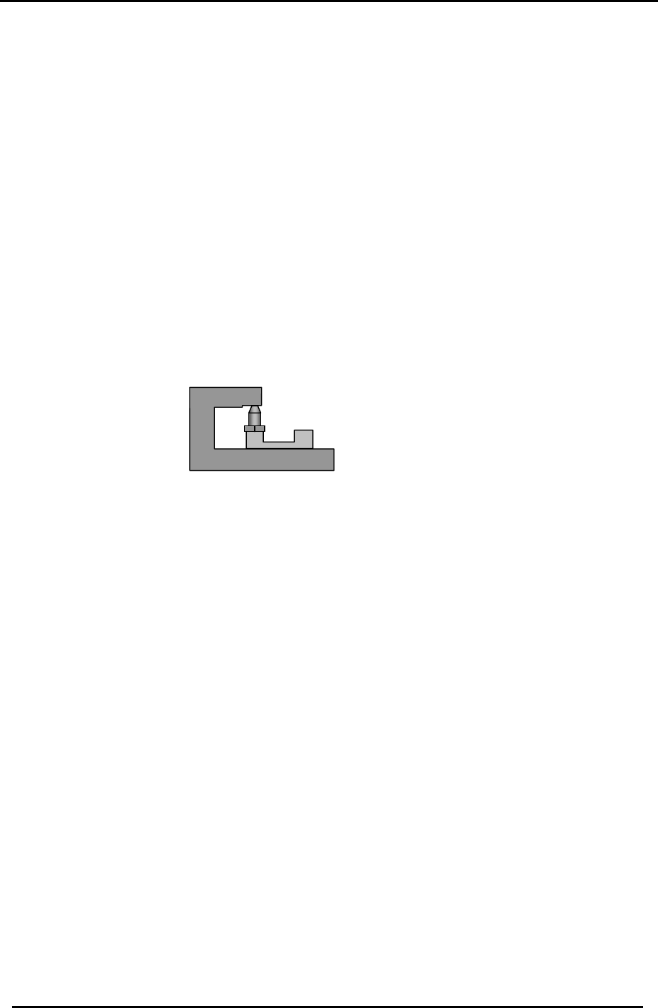
9.1 Backup pin Adjustment
1. Set the height of the Backup pins as specified below.
<Required Jigs>
CP732/733E Backup pin Jig (Jig No. DCPJ0650)
CP742/743(M)E Backup pin Jig (Jig No. DGPJ0450)
CP732/733E Vacuum backup pin Jig (Jig No. DCPJ0661)
CP742/743(M)E Vacuum backup pin Jig (Jig No. DGPJ0460)
Adjust the CP7 Series backup pin height using the appropriate jig.
CP-732/733E Backup pin 26+/-0.05mm
CP-742/743(M)E Backup pin 37+/-0.05mm
CP-732/733E Vacuum backup pin 29+/-0.05mm
CP-742/743(M)E Vacuum backup pin 37+/-0.05mm
Figure 1
Clamp the Fuji096 PCB to the table. Check for any gaps between the bottom surface of the
PCB and the top of the pin.
Note: Check the backup pin height close to the reference and movable rails. (The middle part
of the board may be warped.)
Fuji Machine Mfg. Co., Ltd. (Okazaki)
SMT Equipment Quality Assurance Dept.
CS Section
9-1