CP7 training(6.0) (1).pdf - 第97页
FK-9F98-27 CP-7 Series Traini ng Text for Service Engineers Edition 6.0 Chapter 6. Servo Pack Zero Ad justment and Gain / Motion Check [1/10] Chapter 6 Servo Pack Zero Adju stment and Gain / Motion Check 6.1 Servo Pack P…
FK-9F98-27 CP-7 Series Training Text for Service Engineers
Edition 6.0 Chapter 5. Loader and Conveyor Adjustment [28/28]
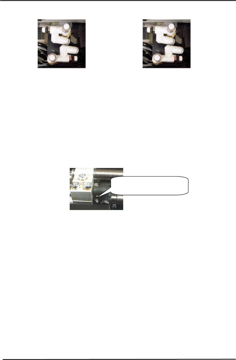
[Adjustment of item “6. IN_C MOVE 14. OUT_C MOVE”]
FWD
OUT-
controller
BWD
IN-
controller
Figure 50
BWD
IN-
controller
FWD
IN-
controller
BWD
OUT-
controller
BWD
OUT-
controller
FWD
OUT-
controller
FWD
IN-
controller
OUT Carrier
(left side front)
IN Carrier
(right side front)
1. Fully open the OUT controller. Adjust the IN side speed controller so that the calibration times reaches
2000 +/- 150 (ms) for CP-732/733E / CP-742/743(M)E)
2. Adjust the OUT controller so that the calibration time reaches 3000 +/- 150(ms) for CP-732/733E and
3500 +/- 150 (ms) for CP-742/743(M)E.
3. Press the E-stop while the carrier is moving forward and backward. Move the carrier again and check if
the moving speed is within the specified time limits.
4. To adjust the cushions of the rod-less cylinder, Turn the adjustment screw 3 revolutions away from the
fully closed position.
[Note]: When using Vacuum Back Up Pins, the loading time is calculated as:
[Loading time measurement value] + 0.72.
(A 360ms software timer is used for timing the vacuum ON/OFF cycle.
Rod-less Cylinder (Cushion)
A
d
j
ustment Screw
Figure 51
Fuji Machine Mfg. Co., Ltd. (Okazaki)
SMT Equipment Quality Assurance Dept.
CS Section
5-28
FK-9F98-27 CP-7 Series Training Text for Service Engineers
Edition 6.0 Chapter 6. Servo Pack Zero Adjustment and Gain / Motion Check [1/10]
Chapter 6 Servo Pack Zero Adjustment and Gain / Motion Check
6.1 Servo Pack Parameter Check
Refer to the servo parameter table (located in the information pocket in each m/c) and check
that all servo pack parameters match the parameter table. If changes are made for some
reason to the servo pack parameters, the M/C must be rebooted in order to register the
change.
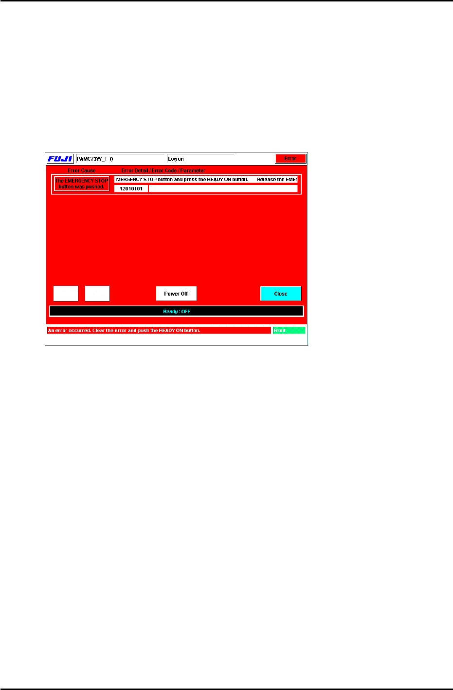
6.2 Servo Pack Zeroing Adjustment
1. Press the [System on] button to boot the M/C. The following display will appear. (Fig.1)
Figure 1
2. Release the emergency stop button and press [Ready ON] to reset the M/C emergency
stop condition. Enter the appropriate password and the display will change to Fig.2. Check
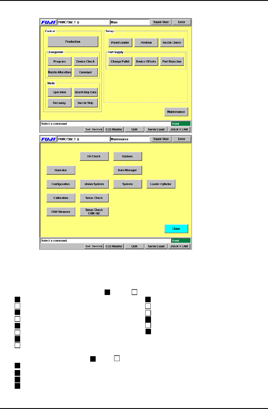
that the cam angle is at 0 degrees and carry out the following commands:
Press: [Position] and specify D-axis escape by pressing the [D1-axis], [D2-axis] button
then press [Start] to carry out D-axis escape.
*Carry out Part rejection by pressing [Part Rejection] Æ [Start].
*Move the XY-table by using [Panel Loader] Æ [Move to Unloading Position]Æ[Start].
Fuji Machine Mfg. Co., Ltd. (Okazaki)
SMT Equipment Quality Assurance Dept.
CS Section
6-1
FK-9F98-27 CP-7 Series Training Text for Service Engineers
Edition 6.0 Chapter 6. Servo Pack Zero Adjustment and Gain / Motion Check [2/10]
3. Next, press [Maintenance] (Fig.2)Æ [I/O check] (Fig.3) to enter the I/O.
Figure 2
Figure 3
4. Set the I/O status as listed below. This will ensure there will be no interference when
performing the procedures in this section.
[Note]: Always carry out I/O operation with the cam at 0 degrees.
<Standard I/O> Output signal ( = ON, = OFF)
Y030 ST1 PICKUP SOL DISENGAGED Y043 MAIN-LIFTER CLAMP
Y031 ST1 PICKUP SOL ENGAGED Y044 MAIN-LIFTER UNCLAMP
Y032 ST1 TAPE FEED SOL DISENGAGED Y058 D1 TABLE STOPPER CLAMP
Y033 ST1 TAPE FEED SOL ENGAGED Y059 D1 TABLE STOPPER UNCLAMP
Y034 ST9 PLACE SOL DISENGAGED Y068 D2 TABLE STOPPER CLAMP
Y035 ST9 PLACE SOL ENGAGED Y069 D2 TABLE STOPPER UNCLAMP
Y036 ST14 NOZZLE CHANGE SOL DISENGAGED
Y037 ST14 NOZZLE CHANGE SOL ENGAGED
<Standard I/O> Input signal ( = ON, = OFF)
X07F D1 CAM CYLINDER LOWER LIMIT CHECK
X081 D1 TABLE STOPPER CAM CYLINDER LOWER LIMIT CHECK
X095 D2 CAM CYLINDER LOWER LIMIT CHECK
X097 D2 TABLE STOPPER CAM CYLINDER LOWER LIMIT CHECK
Fuji Machine Mfg. Co., Ltd. (Okazaki)
SMT Equipment Quality Assurance Dept.
CS Section
6-2