CP7 training(6.0) (1).pdf - 第45页
FK-9F98-27 CP-7 Series T raini ng T ext for Service Engineers Edition 6.0 Chapter 3. X, Y , Z and D-axes Adjustm ent [31/36] 3.14 Cam Box Positioning Check 1. Attach the positioning jig o nto the “A” shaft. Set the cam a…
FK-9F98-27 CP-7 Series Training Text for Service Engineers
Edition 6.0 Chapter 3. X, Y, Z and D-axes Adjustment [30/36]
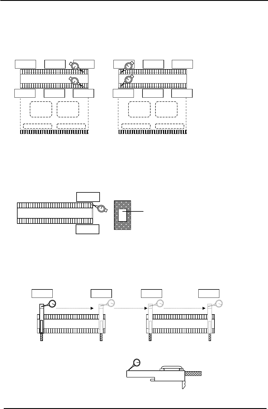
3.13 D-axis Pallet Flatness Measurement
1. Flatness of the top plates on the pallets is important to maintain consistent pick up. Set up two dial
gauges as pictured and indicate the top surface of the feeder plate at the positions illustrated in
Fig.41. (Tolerance: within 0.10mm)
0
D2Pallet
D1Pallet
0
0
Figure 41
2. If the flatness measurement is out of tolerance, ensure that there are no components caught
between the D-axis base plate and pallet. (if problems persist, replace the pallet)
3. Set a dial gauge and block on the machine base and check the flatness from A to B.
(Tolerance: within 0.05mm)
D1 Pallet
0
A
Dial Gauge Block
Jig No.: DCPJ0750
Figure 42
4. Install the feeder height jig at the second and next to last feeder slots on each pallet. Check the
flatness of the D1 and D2 pallets. (4 points in total) (Tolerance: within 0.05mm)
Feeder Height Jig
Jig No.: Z5413AWPJ9270
Figure 43
D1 Pallet
0
D2 Pallet
Fuji Machine Mfg. Co., Ltd. (Okazaki)
SMT Equipment Quality Assurance Dept.
CS Section
3-30
FK-9F98-27 CP-7 Series Training Text for Service Engineers
Edition 6.0 Chapter 3. X, Y, Z and D-axes Adjustment [31/36]
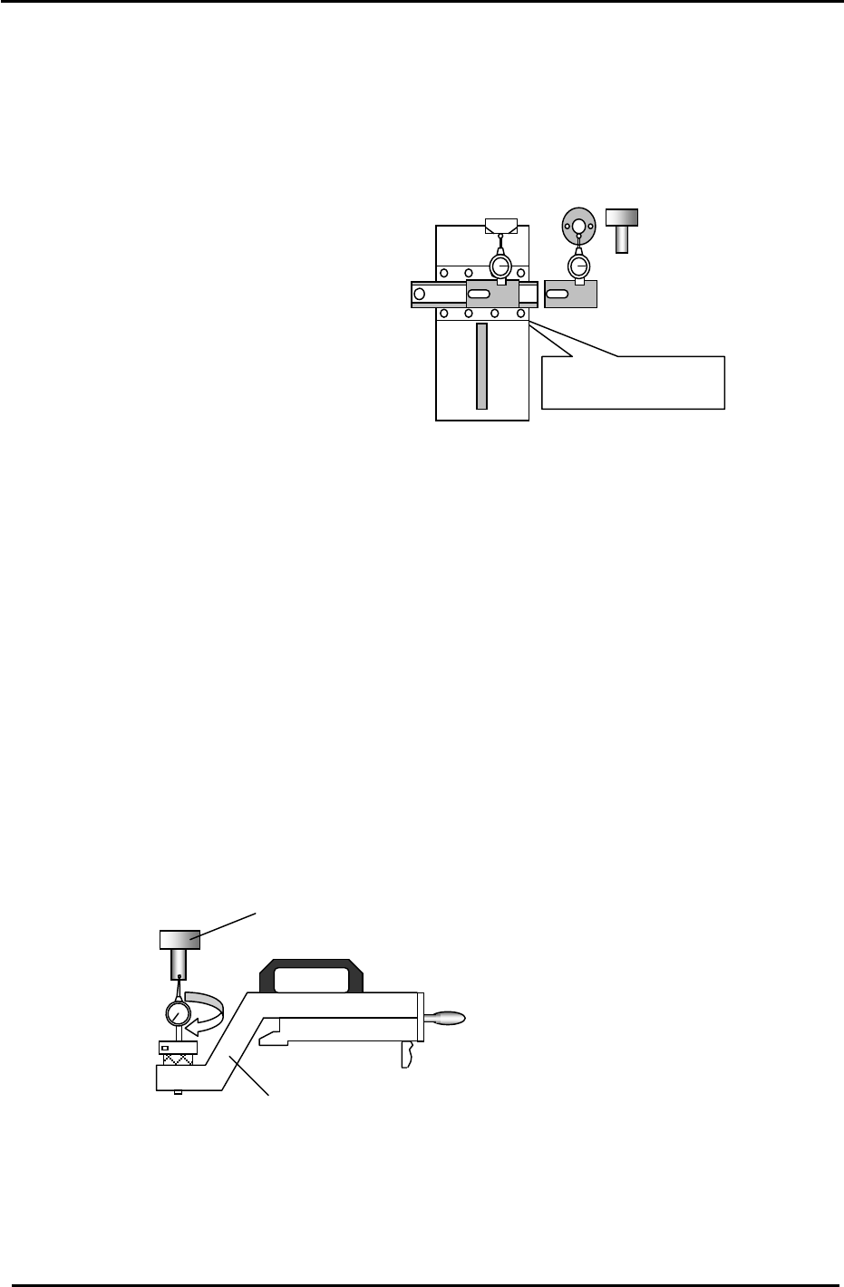
3.14 Cam Box Positioning Check
1. Attach the positioning jig onto the “A” shaft. Set the cam at 0 and turn the Pick-up valve ON. (Y031)
2. Position the A shaft at station 1 and set the cam to 170 degrees.
3. Install the cam box alignment jig on the pallet.
0 to 0.05mm
(Tolerance: 0 to + 0.05mm)
Do not inch with the jig
attached to the
p
allet.
JIG A
Cam box alignment
Jig No.: ADCPJ8271
(Jig No.:ADCPJ8130)
4. Check the cam box position at slots:
3 & 28 of D1 & D2 (CP-732/733E)
3 & 38 of D1 & D2 (CP-742ME)
3 & 68 of D1 & D2 (CP-742E)
Figure 44
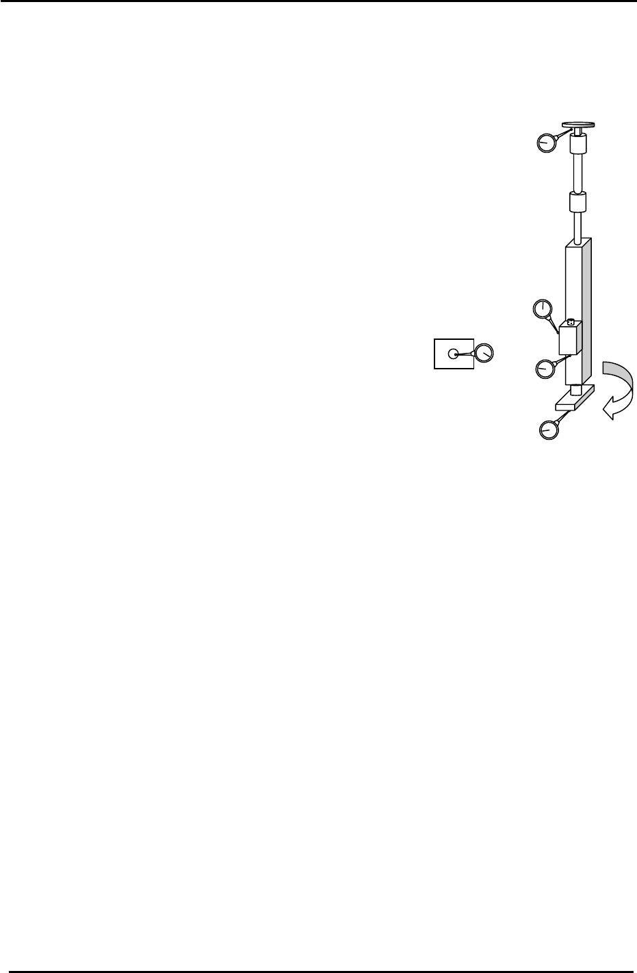
3.15 Pick-up Position Calibration
1. Attach the positioning jig onto the A Shaft.
(Jig No.:ADCPJ8130)
2. Set the “Pick up Position” jig on the D1/D2 table at slot No.1. (Jig No.:ADCCPJ8251)
3. Turn the Pick-up valve ON (Y031) and set the cam to 170 degrees at Sta. 1.
4. Balance the dial gauge on both sides of the positioning jig in the X-direction.
When the gauge is balanced on each side, this becomes pick up position D1/D2.
Press: [Maintenance] → [Calibration] → [Pick Up Reference] → [D1/D2] → [Set]
(Jig No.:ADCPJ8130)
“Pick up pos” jig
(Jig No.:ADCCPJ8251)
Figure 45
Fuji Machine Mfg. Co., Ltd. (Okazaki)
SMT Equipment Quality Assurance Dept.
CS Section
3-31
FK-9F98-27 CP-7 Series Training Text for Service Engineers
Edition 6.0 Chapter 3. X, Y, Z and D-axes Adjustment [32/36]
3.16 Shaft Measurement Check
The following steps explain how to check various items on the nozzle shafts. These measurements are
required when carrying out adjustments in Chapter 4.
1. Set the Cam angle to 0 degrees.
2. Turn the 9
th
station place solenoid ON. (Y035)
3. Using shaft A as the zero reference, measure the height of the shaft
flange (1) for all the shafts A to P. Measure with the cam at 180
degrees. Push down on the flange slightly with a finger so the
position of the shaft remains consistent.
(Tolerance: < 0.05mm)
Measure both ends of the shaft flange to ensure it is flat; the
difference between the two ends of the flange should be
0.01mm or less.
4. Use spool A as the reference and measure the height of
spools A to P. Note that the height of the spool should be
measured when it is at the upper limit (2). Measure at 180
degrees. Push down on the flange slightly with a finger so the
position of the shafts remains consistent.
(Tolerance: < 0.15mm)
5. Measure the stroke of the 10
th
station. (at 200 degrees) Put the
dial gauge on the under side underside of the clutch (3). Find
the lowest shaft (the shaft that pushes down the least) and set
the stroke for this shaft within the range of 0.3 to 0.35mm. Note
that 0.31mm is the ideal value. Also be aware that when rotating
the shaft the stroke amount will change; set the stroke where the
clutch underside is lowest. When rotating the shaft the
fluctuation in the stroke amount should be less than 0.05mm.
Bottom view of
spool valve.
2
3
4
1
Figure 46
6. As mentioned above, the stroke of the lowest shaft should be
within the range of 0.3 to 0.35mm. The stroke of all the other
shafts must be within the range 0.3 (Min) to 0.45mm.(Max)
7. Measure the position spool valves A to P (4) in the X- direction.
Tolerance: within 0.1mm. If out of range, loosen the two
screws on the valve and reposition. (Torque = 0.8N.m)
8. For the adjustments that follow in Chapter 4, it is necessary to identify
the following three shafts:
1. Finding the low shaft.
2. Establishing the mid shaft. (Average deflection)
3. Finding the shaft with the low spool valve.
4. Finding the shaft with the highest spool. (used for station 13 adjustment)
Fuji Machine Mfg. Co., Ltd. (Okazaki)
SMT Equipment Quality Assurance Dept.
CS Section
3-32