CP7 training(6.0) (1).pdf - 第103页
FK-9F98-27 CP-7 Series Traini ng Text for Service Engineers Edition 6.0 Chapter 6. Servo Pack Zero Ad justment and Gain / Motion Check [7/10] Figure 7 Figure 8 Fuji Machine Mfg. Co., Ltd. (Okazaki) SMT Equipment Quality …
FK-9F98-27 CP-7 Series Training Text for Service Engineers
Edition 6.0 Chapter 6. Servo Pack Zero Adjustment and Gain / Motion Check [6/10]
6.5 Servo Pack Gain and Motion Check Procedure
[
Note]: Select only one axis at a time from the “Select Tuning Axis” field.
1) When an axis is selected (Fig.4), each parameter for the axis will be displayed on the “Select
Parameter List”. The parameter from the “Select Parameter List” can be changed by pressing
the [UP] and [DOWN] keys in the “Parameter Manager”.
First, press the intended parameter and then press [Decision] from the “Parameter Manager”.
The parameter selected in the “Decision parameter” will be displayed.
When [Tuning] is pressed, axis operation can be carried out by the parameter displayed as the
“Decision Parameter”.
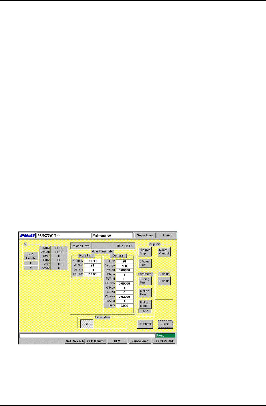
2) Each time the [Tuning Prm.] from “Parameter” is selected, the display switches between
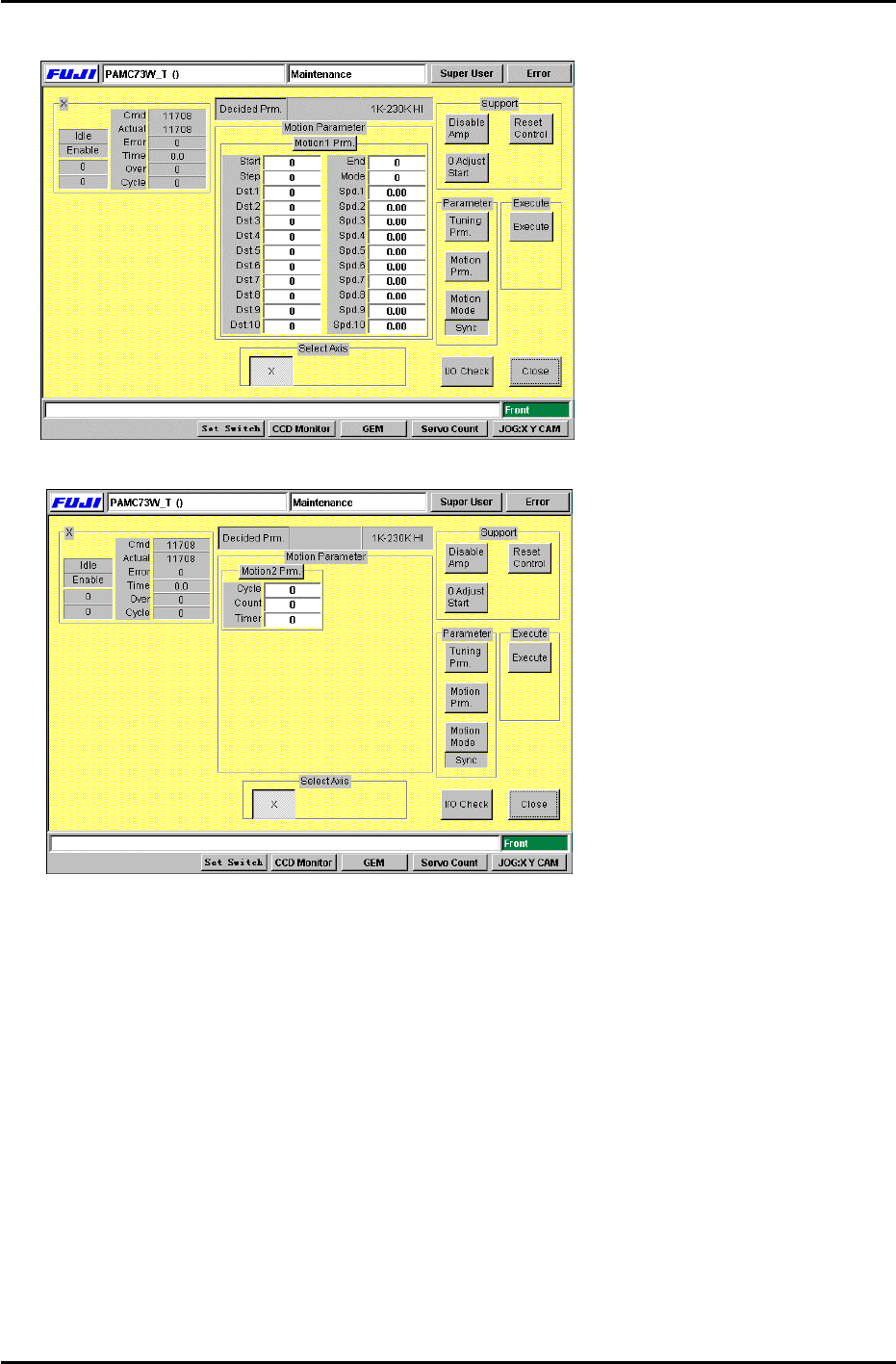
Fig.5 and fig.6. Each time [Motion Prm.] is pressed, the display changes between Fig.7 and
Fig.8. Each time [Motion Mode] is pressed, the display under the button changes between
“Sync”, “Interp”, “Unsync”, “Timer” one by one. The set value is always set to “Sync”,
[Caution]: Do not change the [Move Parameter] and [Gain Parameter] in Fig.5 and Fig.6.
3) After [Motion1 Prm.] is pressed in Fig.7, values can be entered into [Start], [End]. Enter the
values for [Start] and [End] according to the gain test adjustment table.
Carry out the same procedure for Fig.8 [Motion2 Prm.]. Press and enter the values for
[Cycle], and [Timer]. Enter 1 for [Cycle mode] and 500 for [Interval timer].
The machine [Start] button will blink after [Execute] is pressed. After [Start] is pressed, the
axis will begin to move. Press [Cycle stop] to stop movement.
During movement, the amount of traverse time (ms) and overshoot (pulse) are displayed in
“Time” and “Over”. Check that the values fit within the values shown in the gain test
adjustment table.
Figure 6
Fuji Machine Mfg. Co., Ltd. (Okazaki)
SMT Equipment Quality Assurance Dept.
CS Section
6-6
FK-9F98-27 CP-7 Series Training Text for Service Engineers
Edition 6.0 Chapter 6. Servo Pack Zero Adjustment and Gain / Motion Check [7/10]
Figure 7
Figure 8
Fuji Machine Mfg. Co., Ltd. (Okazaki)
SMT Equipment Quality Assurance Dept.
CS Section
6-7
FK-9F98-27 CP-7 Series Training Text for Service Engineers
Edition 6.0 Chapter 6. Servo Pack Zero Adjustment and Gain / Motion Check [8/10]
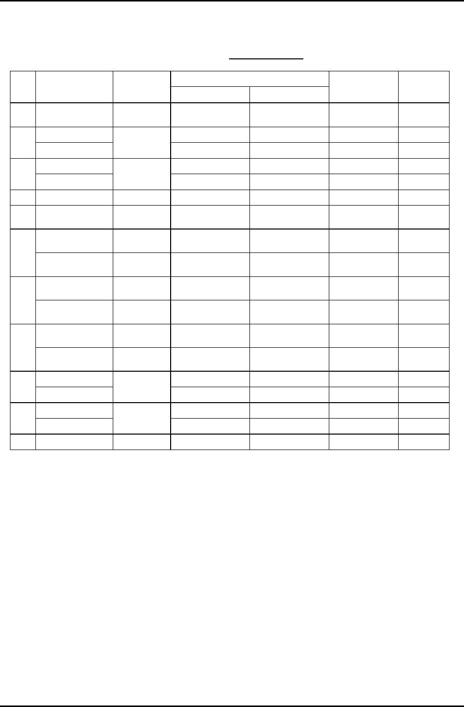
Gain Test Table
*CP-732/3E
Note: This table applies to application versions
T1.00a & higher
Value entered
Axis Parameter
Adj.
condition
Start End
Traverse time
(ms)
Overshoot
(pulse)
C Auto
Current counter
value
Start value
+12000
137.0 to 140.0 40 to 50
6K-230K UHi 10000 17100 46.0 to 49.0 0 to 10
X
IK-230K MID
Cam @ 0
10000 13000 46.0 to 49.0 0 to 10
5K-197.5K UHI 10000 17100 46.0 to 49.0 0 to 10
Y
500-197.5K MID
Cam @ 0
10000 13000 46.0 to 49.0 0 to 10
Z Auto Cam @ 0 1000 1595 46.0 to 49.0 0 to 5
PQ ROTATION 100 Cam @180 Current counter
value
Start value
+3600
34.5 to 37.5 0 to 10
0.4K-1.3K
ROT 100
Cam @180 Current counter
value
Start value
+1300
30.5 to 33.5 0 to 10
FQ
RETURN Cam @ 0 Current counter
value
Start value +450 12.5 to 15.5 0 to 10
ROTATION 100 Cam @180 Current counter
value
Start value
+3600
34.5 to 37.5 0 to 10
RQ
RETURN Cam @ 0 Current counter
value
Start value +450 12.5 to 15.5 0 to 10
ROTATION Cam @180 Current counter
value
Start value
+1200
12.0 to 15.0 0 to 10
NC
RETURN Cam @ 0 Current counter
value
Start value
+1200
25.0 to 28.0 0 to 10
5K-9K STD L 0 8250 77.0 to 80.0 0 to 10
D1
WEIGHT MEAS
Cam @ 0 &
Empty table
0 3000 54.0 to 57.0 0 to 10
5K-9K STD L 0 8250 77.0 to 80.0 0 to 10
D2
WEIGHT MEAS
Cam @ 0 &
Empty table
0 3000 54.0 to 57.0 0 to 10
NZ Auto Cam @ 0 4000 10750 46.0 to 49.0 0 to10
Enter 1 in [Cycle Mode] and 500 in [Timer] for all Axes.
Fuji Machine Mfg. Co., Ltd. (Okazaki)
SMT Equipment Quality Assurance Dept.
CS Section
6-8