CP7 training(6.0) (1).pdf - 第129页
FK-9F98-27 CP-7 Series T raini ng T ext for Service Engineers Edition 6.0 Chapter 10. Options [2/6] 10.1.1 Machine Setting T o enable the “Parts Height” check fun ction, enter the following comm ands: Press: Maintenance …
FK-9F98-27 CP-7 Series Training Text for Service Engineers
Edition 6.0 Chapter 10. Options [1/6]
Chapter 10 Options
10.1 Parts Thickness Confirmation Sensor Adjustment
The parts thickness sensor is an option designed to provide more reliable placement by measuring the
parts thickness and nozzle length to determine the level of abrasion on the nozzle tips plus check the
part pick-up condition.
By periodically measuring the nozzle length, any nozzle abrasion can be reflected in the pick-up height
data, and any nozzles exceeding a specified level of abrasion can be automatically skipped, with
nozzle exchange guidance issued to the operator.
By measuring the thickness of parts held on the nozzles, the results are fed back to the pick-up height
for consistency of pressure on the parts at pick-up. Any parts exceeding the specified tolerance will
cause an error and are automatically skipped. This feature is particularly effective in the monitoring of
the pick-up status of microchips such as 0603’s (in. 0201’s) for slanted and “tombstone” pick-ups.
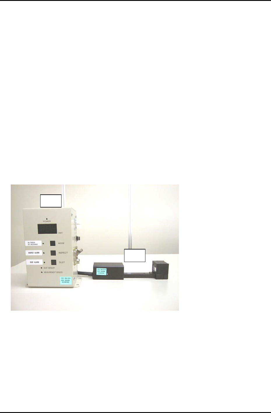
The parts thickness confirmation sensor system is comprised of the following parts.
• Controller Unit (# 1)
• Sensor Head (# 2)
• Compatible m/c control software version (V1.17 or later).
# 2
# 1
Figure 1
Fuji Machine Mfg. Co., Ltd. Okazaki
SMT Equipment Quality Assurance Dept.
CS Section
10-1
FK-9F98-27 CP-7 Series Training Text for Service Engineers
Edition 6.0 Chapter 10. Options [2/6]
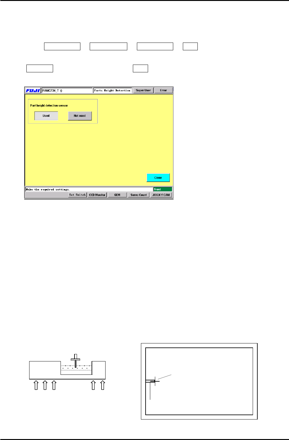
10.1.1 Machine Setting
To enable the “Parts Height” check function, enter the following commands:
Press: Maintenance Æ Configuration Æ Parts Height Æ Used
Note: When re- installing the system software, the default setting is automatically set to
Not Used. Therefore, be sure to set to Used after installing the system software.
Figure 2
10.1.2 Sensor Head Alignment
Follow the procedure below in order to align the nozzle and sensor head appropriately.
1. Connect a portable TV monitor to the output jack on the right side of the controller unit.
2. Place the ”A” shaft at the 6
th
station [parts thickness confirmation sensor] with a 0.7mm
nozzle and set the cam angle to 197 degrees.
3. To display the nozzle image on the monitor, press: [MODE](LED ON) on the sensor amplifier.
Loosen the 5 mounting bolts (Fig.3) for the sensor head (under the cutter plate) and adjust so
the nozzle appears at the left side center of the monitor. (Fig.4)
4. Tighten the mounting bolts using a 3.9Nm torque wrench.
5. Press [MODE] once more Æ [INSPECT], the crosshairs will appear on the display, check
the nozzle center position. Repeat step 3 if the nozzle image is not centered properly.
Nozzle Image
Portable Monitor
Crosshairs
Sensor Head
5 x 3mm Mounting Bolts
Figure 3
Figure 4
Fuji Machine Mfg. Co., Ltd. Okazaki
SMT Equipment Quality Assurance Dept.
CS Section
10-2
FK-9F98-27 CP-7 Series Training Text for Service Engineers
Edition 6.0 Chapter 10. Options [3/6]
10.1.3 Sensor Amplifier Output Voltage Adjustment
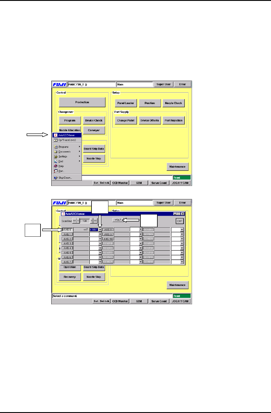
Follow the procedure below in order to set the Nozzle Length Unit amplifier control voltages.
1. Connect the keyboard to the machine. (connect only when the m/c power is OFF)
2. Press the [Windows key] on the keyboard and go to the voltage adjustment display by
selecting, [AxisADCViewer] (Fig 5) Æ [Axis 0] (Fig.6 #1) Æ [select ±10V] (Fig.6 #2) Æ [VOLT]
(Fig.6 #3)
Figure 5
#2
# 1
#3
Figure 6
Fuji Machine Mfg. Co., Ltd. Okazaki
SMT Equipment Quality Assurance Dept.
CS Section
10-3