CP7 training(6.0) (1).pdf - 第54页
FK-9F98-27 CP-7 Series T raini ng T ext for Service Engineers Edition 6.0 Chapter 4. S tation Adjustment [5/28] 4.4 Head A Check Sensor Adjustment 1. Adjust the position of the sensor bracket so that the head “A” sensor …
FK-9F98-27 CP-7 Series Training Text for Service Engineers
Edition 6.0 Chapter 4. Station Adjustment [4/28]
10. Taking care to ensure that the jig does not interfere with the adjacent shafts, bring shaft A to the
3
rd
station at 200 degrees.
11. Loosen the two 5.5mm hex bolts above the third station clutch (fig. 8).
5.5mm
Hex head bolt
1
Figure 8
12. Rotate the position of the clutch (1) until the 3
rd
station origin jig is parallel to the D axis. Use a
dial gauge on the D axis to measure the surface of the jig. (Tolerance: 0 +/- 0.01mm)
13. Having locked the two 5.5mm hex bolts, and secured the clutch angle, double check that the jig
is still parallel to the D axis. Do this by rotating the jig past the 4
th
station, then back beyond the
3
rd
station, and finally forward to mesh once again with the 3rd station at 200 degrees
Fuji Machine Mfg. Co., Ltd. (Okazaki)
SMT Equipment Quality Assurance Dept.
CS Section
4-4
FK-9F98-27 CP-7 Series Training Text for Service Engineers
Edition 6.0 Chapter 4. Station Adjustment [5/28]
4.4 Head A Check Sensor
Adjustment
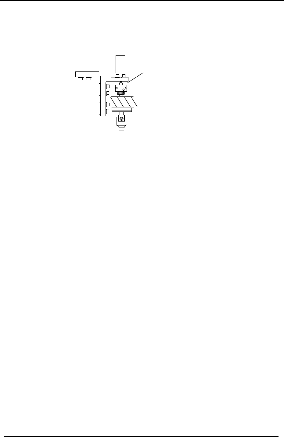
1. Adjust the position of the sensor bracket so that the head “A” sensor turns OFF between 318
to 320 degrees.
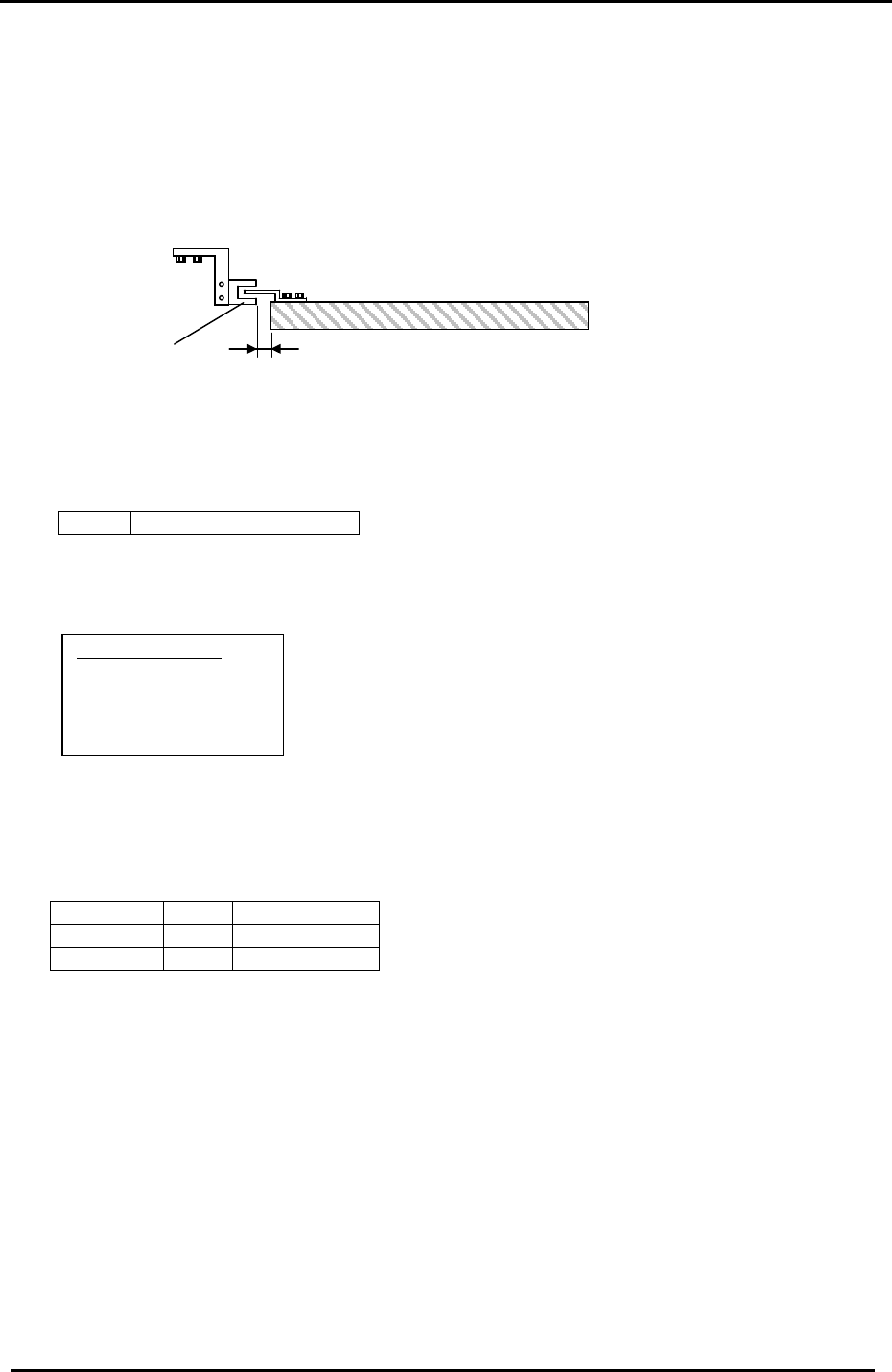
2. Note that the target clearance between the sensor and the helical gear is > 0.5mm.
HELICAL GEAR
> 0.5mm
Head A
Sensor
Figure 9
3. Check the sensor reaction in I/O.
<I/O Æ Standard Æ IN>
X04F ST 11 HEAD A CHECK
4.5 PQ, FQ, RQ-axes Timing Belt Tension
Equipment Checklist:
1- 5mm T-wrench
1- 5mm L-wrench
1- 8mm spanner
1- Tension Meter
1. Use a tension meter to measure the tension of the 2
nd
, 8
th
and 10
th
station timing belts. The
target values are shown below:
Station 2 PQ 220 +/- 5 Hz
Station 8 FQ 242 +/- 5 Hz
Station 10 RQ 214 +/- 5 Hz
4.6 PQ, FQ, RQ-axes Calibration Data Setting
(0.05 deg/pulse)
1. Note that this adjustment should be performed with the servo power OFF.
2. Before setting the Calibration Data, the tension of the timing belts must be set.
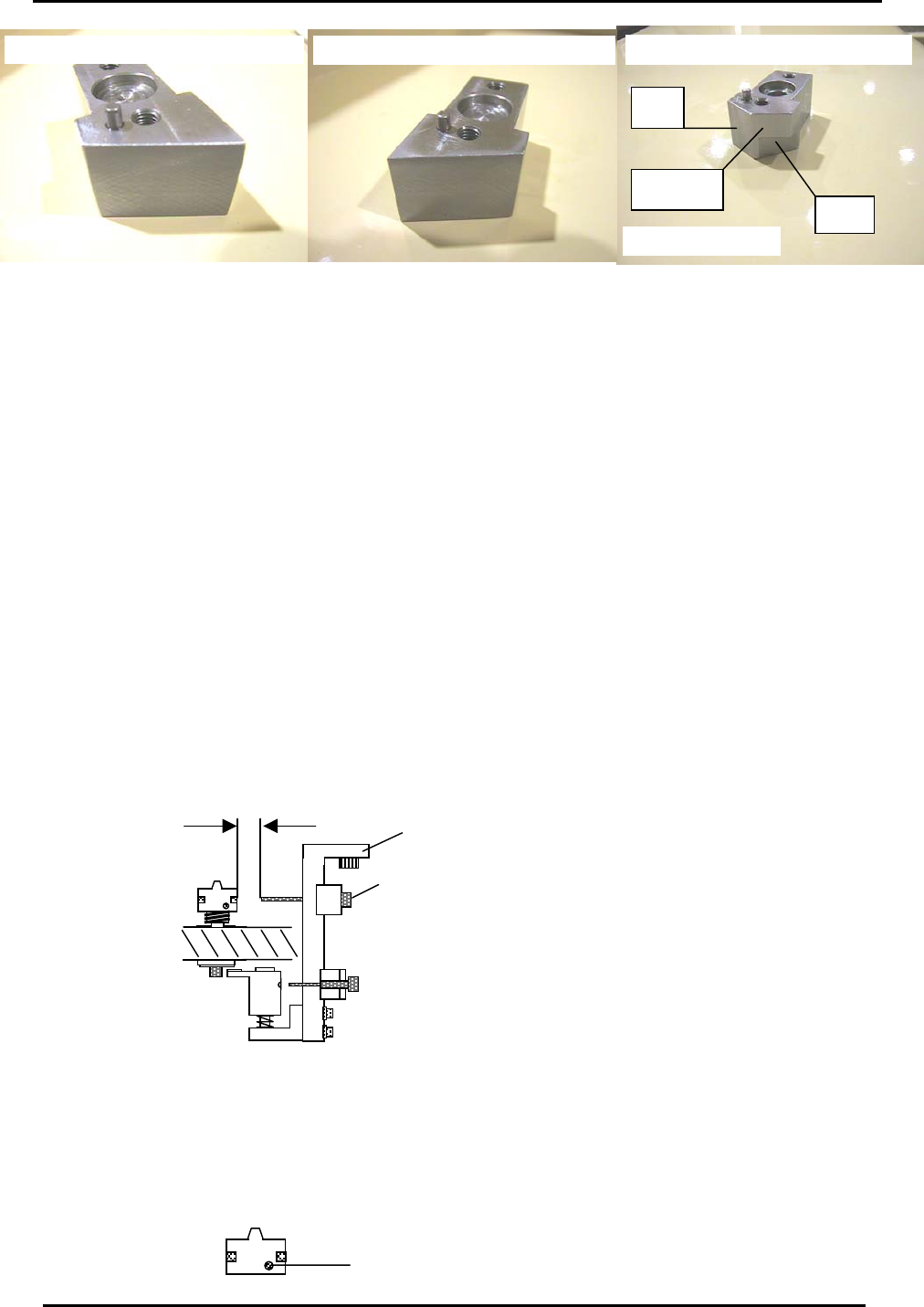
3. Use the jigs below to measure the origin positions of PQ, FQ and RQ. The common jig is
suitable for measuring the origin positions of all three axes.
Fuji Machine Mfg. Co., Ltd. (Okazaki)
SMT Equipment Quality Assurance Dept.
CS Section
4-5
FK-9F98-27 CP-7 Series Training Text for Service Engineers
Edition 6.0 Chapter 4. Station Adjustment [6/28]
Common Jig for stations 2, 3, 8 and 10
Jig No. ADCPJ8232
FQ
PQ + RQ
RQ and PQ Ori
g
in Ji
g
. Ji
g
No DCPJ0200
St 3
FQ Ori
g
in Position Ji
g
. Ji
g
No DCPJ0200
Figure 10
4. Confirm that the ”A “ shaft assembly is properly aligned, then place the relevant jig on shaft A.
5. The origin position of each station should be measured at 200 degrees. When rotating the cam
with a jig attached, ensure the jig does not interfere with neighboring shafts.
6. Use a dial gauge on the X or D axis to find the origin position of PQ, FQ & RQ. The origin position
Calibration Data should be within 0 +/- 500 pulses. At first, rotate the axis to zero pulses and then
align with the jig.
7. Once the origin position is established, input the Calibration Data by performing the following
commands:
Press: [Maintenance] → [Calibration] → [Origin Pos Offset] → [PQ], [FQ], or [RQ] → [Set].
8. Finally, receive the Calibration Data to the host PC.
4.7 10
th
Station Origin Position Sensor Adjustment
1. Select a shaft with an average stroke amount (mid-shaft).
2. Set a gap of 5mm between the nozzle origin sensor and the clutch head by moving the fiber
sensor in or out.
Nozzle O
5mm
ri
g
in Senso
r
Bracket 1
Figure 11
3. Set the RQ pulse count to the RQ Original Position as measured in step 4.6.
4. Engage the mid-shaft with the 10
th
station at 200 degrees.
5. Align the fiber sensor beam in the center of the nozzle origin hole by adjusting bracket 1.
A
li
g
n in the cente
r
Fuji Machine Mfg. Co., Ltd. (Okazaki)
SMT Equipment Quality Assurance Dept.
CS Section
4-6