CP7 training(6.0) (1).pdf - 第127页
FK-9F98-27 CP-7 Series T raini ng T ext for Service Engineers Edition 6.0 Chapter 9, Miscellaneous Adjustments [5/6] 9.4 PCB Set Check Sensor Adjustment (CP-742/743(M)E) 1. Adjust the sensor BKT so that the light ax is c…
FK-9F98-27 CP-7 Series Training Text for Service Engineers
Edition 6.0 Chapter 9, Miscellaneous Adjustments [4/6]
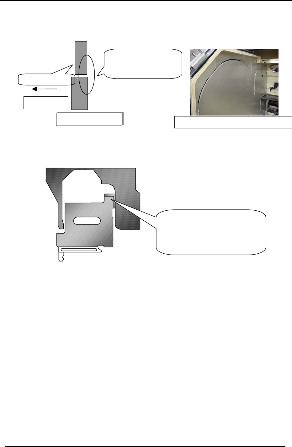
3. Park the D-axis pallets, align the D-axis pallet cover and D-axis escape position
aluminum plate as indicated in Fig.6.
4. Install as spacer jig on the D-axis, and adjust as indicated in Fig.7.
5. After adjustment, move the D-axis and verify that nothing interferes with the D-axis
pallet covers.
Cross- Section
Plates ali
g
n toward center of machine
Figure 7
Figure 6
Adjust the clearance between the
D-axis (at the escape position) and
the cover using a spacer jig.
(Jig No.: Z9526ADCPJ8640)
Pallet Side
Adjust the plates to
align toward the
center of the machine
.
D
-ax
i
s cover
Fuji Machine Mfg. Co., Ltd. (Okazaki)
SMT Equipment Quality Assurance Dept.
CS Section
9-4
FK-9F98-27 CP-7 Series Training Text for Service Engineers
Edition 6.0 Chapter 9, Miscellaneous Adjustments [5/6]
9.4 PCB Set Check Sensor Adjustment (CP-742/743(M)E)
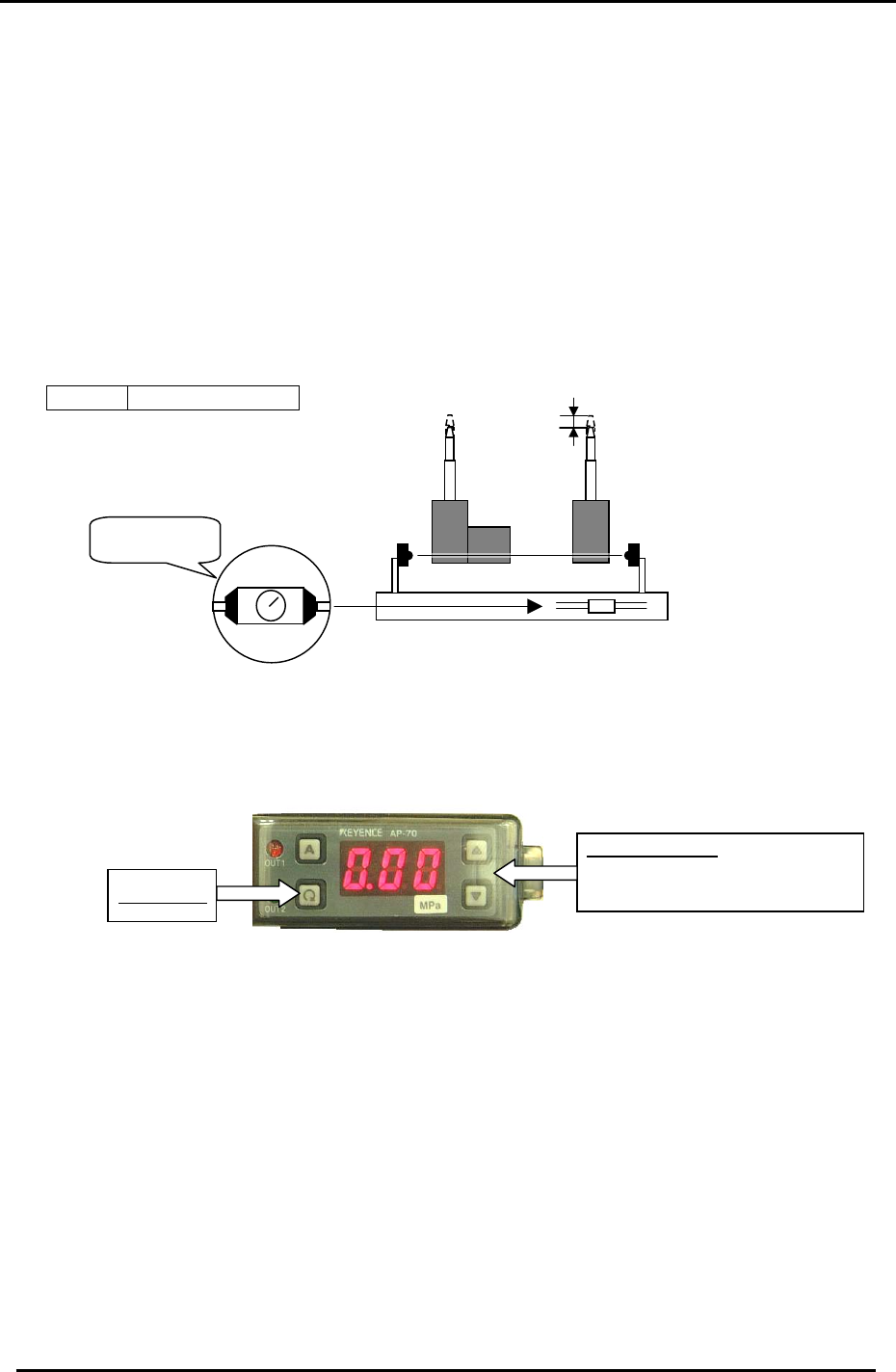
1. Adjust the sensor BKT so that the light axis comes to the center of the reference pin
and secondary pin block hole.
2. Set the sensor so it turns OFF when both the reference and adjustable pins move
down 1.0 to 1.5mm.
3. As for the adjustable pin, the sensor should react at maximum, mid and minimum
pitches. Make sure that the green LED is always ON.
4. Check the sensor reaction in I/O
< I/O Æ Standard I/O Æ IN>
X059 PCB SET OK
1.0 to 1.5 mm
Figure 8
Set to MAX.
MIN
MAX
9.5 Oil Pressure Sensor Amp Adjustment
Up & Down Keys
To change setting values and set
output levels.
Setting Key
Follow the directions below to set the sensor amp operating parameters:
1. Press and hold the “A” key and Up arrow (▲)simultaneously to unlock the amp. (UNL)
2. Press and hold the setting key for 3 sec and set the pressure display to AP6.
3. Press the setting key to set the display to F-4.
4. Press the setting key to set the display to con.
5. Press the setting key twice to display H.
6. Press the up/down to set the high value to H 0.40.
7. Press the setting key twice to display L .
8. Press the up/down to set the low value to L 0.20.
9. Press the setting key to display P 000.
10. Press the setting key to view the current pressure value.
11. Press and hold the “A” key and Up arrow (▲) simultaneously to lock the amp. (LOC)
Fuji Machine Mfg. Co., Ltd. (Okazaki)
SMT Equipment Quality Assurance Dept.
CS Section
9-5
FK-9F98-27 CP-7 Series Training Text for Service Engineers
Edition 6.0 Chapter 10. Options [1/6]
Chapter 10 Options
10.1 Parts Thickness Confirmation Sensor Adjustment
The parts thickness sensor is an option designed to provide more reliable placement by measuring the
parts thickness and nozzle length to determine the level of abrasion on the nozzle tips plus check the
part pick-up condition.
By periodically measuring the nozzle length, any nozzle abrasion can be reflected in the pick-up height
data, and any nozzles exceeding a specified level of abrasion can be automatically skipped, with
nozzle exchange guidance issued to the operator.
By measuring the thickness of parts held on the nozzles, the results are fed back to the pick-up height
for consistency of pressure on the parts at pick-up. Any parts exceeding the specified tolerance will
cause an error and are automatically skipped. This feature is particularly effective in the monitoring of
the pick-up status of microchips such as 0603’s (in. 0201’s) for slanted and “tombstone” pick-ups.
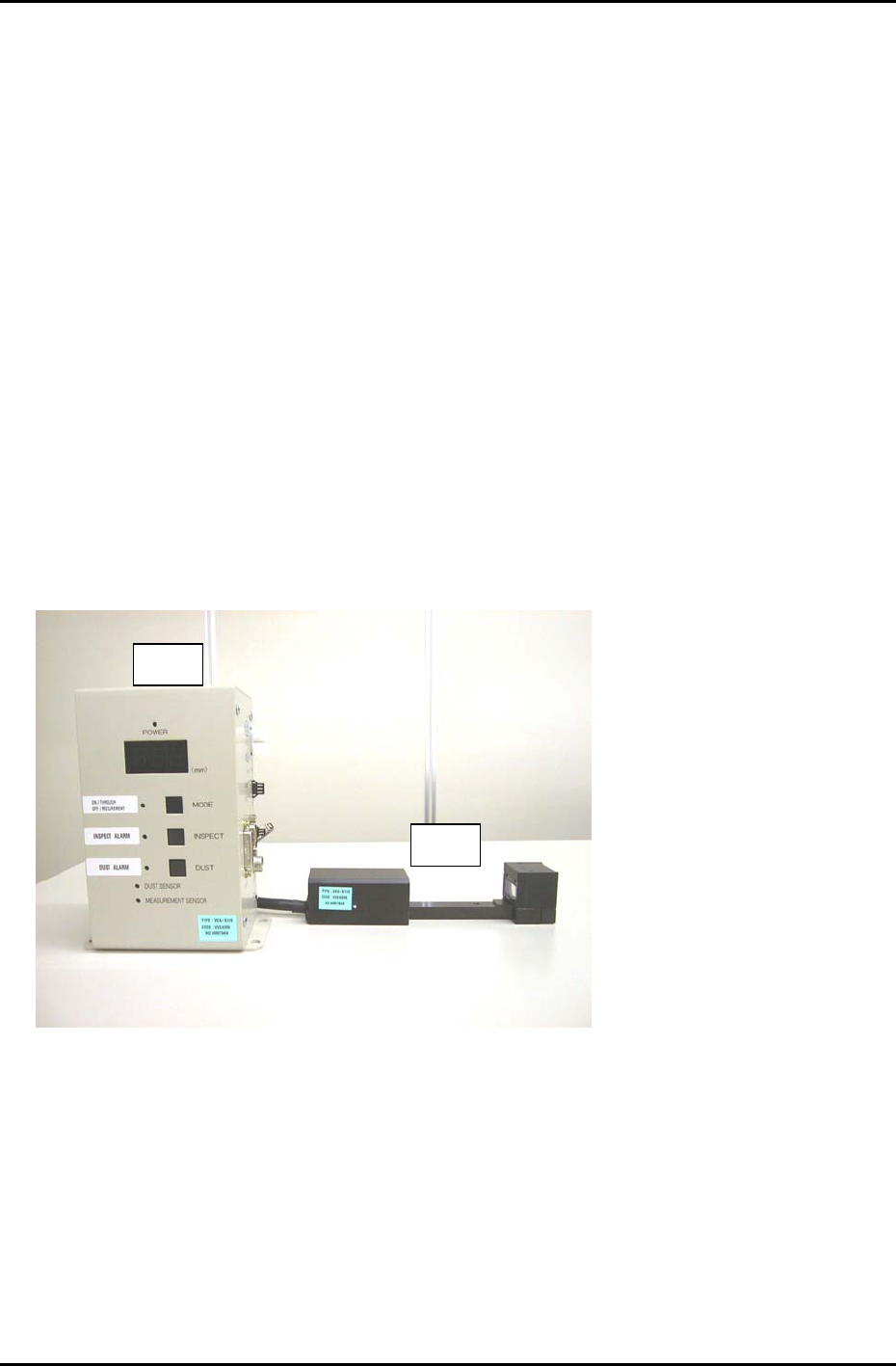
The parts thickness confirmation sensor system is comprised of the following parts.
• Controller Unit (# 1)
• Sensor Head (# 2)
• Compatible m/c control software version (V1.17 or later).
# 2
# 1
Figure 1
Fuji Machine Mfg. Co., Ltd. Okazaki
SMT Equipment Quality Assurance Dept.
CS Section
10-1