CP7 training(6.0) (1).pdf - 第77页
FK-9F98-27 CP-7 Series T raining T ext for Service Engineers Edition 6.0 Chapter 5. Loader and Conveyor Adjustment [9/28] 5.13 Z-axis Mechanical V alve Adjustment 1. Adjust the mechanical valve and dog for the moveable r…
FK-9F98-27 CP-7 Series Training Text for Service Engineers
Edition 6.0 Chapter 4. Station Adjustment [27/28]
4.25 Stations 1 & 9 Upward and Downward End Sensor Adjustment
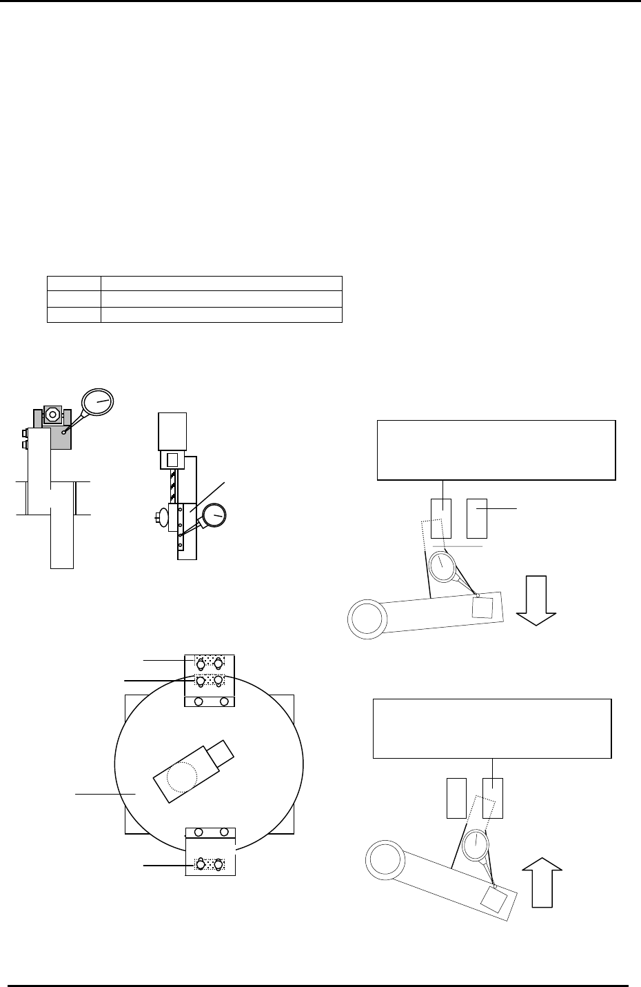
1. At 0 degrees, turn ON the solenoid valve for Stations 1 & 9
nozzle up/down.
2. For Stations 1& 9 Up End sensor adjustment, set the cam at 0 degrees. Set a dial indicator at
the tip of the cam lever. Adjust the sensor bracket so that the upper limit sensor turns OFF
when the lever descends 0.30 to 0.40mm.
3. For the Station 9 Down End sensor adjustment, set the cam at 195 degrees. Set the dial
gauge at the tip of the cam lever. Adjust the downward end sensor to turn OFF when the lever
ascends 0.30 to 0.40mm.
4. Confirm sensor reaction by I/O.
<I/O Æ Standard Æ IN>
X030 ST1 NOZZLE UPPER LIMIT CHECK
X032 ST9 NOZZLE UPPER LIMIT CHECK
X033 ST9 NOZZLE LOWER LIMIT CHECK
Note: For further information and illustrations on this procedure, refer to the CP-7 series Mechanical
Reference Manual.
Station 9
NZ
Sensor flag
Down end sensor
The up end sensor should turn
OFF when the lever lowers 0.3 to
0.4mm from 0 de
g
rees.
Station 1
Noz. Up/Down
Figure 46
Down end sensor
Up end sensor
Station 9
Station 1
Nozzle index unit
Up end sensor
Figure 47
Figure 48
Figure 49
The down end sensor should turn
OFF when the lever lifts 0.3 to
0.4mm from 195 de
g
rees.
Fuji Machine Mfg. Co., Ltd. (Okazaki)
SMT Equipment Quality Assurance Dept.
CS Section
4-27
FK-9F98-27 CP-7 Series Training Text for Service Engineers
Edition 6.0 Chapter 5. Loader and Conveyor Adjustment [9/28]
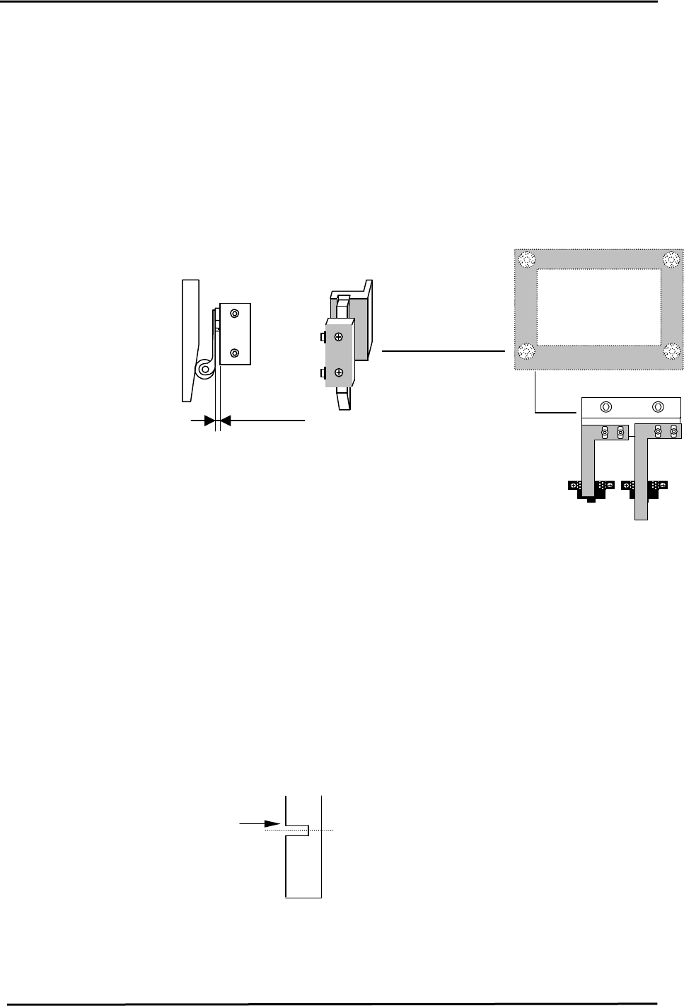
5.13 Z-axis Mechanical Valve Adjustment
1. Adjust the mechanical valve and dog for the moveable rail locking cylinders as follows.
The moveable rail on the main table should lock when the Z-axis is positioned at;
[ZL lower – 650 +/- 50 pulses.]
2. If out of range, move the dog up or down until the rail clamps within the specified range.
3. After adjustment, make sure the pneumatic swich lever has 1 to 2mm of play. Too much
pressure on the lever will result in damage to the pneumatic switch.
5.14 Z-axis Sensor Adjustment
MOT Sensor
X05E MAIN LIFTER
MIDDLE OT
1 to 2mm
Figure 16
Upper end limit
X05C XY-TABLE LOADING
HEIGHT CHECK
1. Set the middle overtravel sensor flag at [ Z0 + 250 ± 50pls.]
2. Calculate the Middle Loading Position as follows:
CP-732/733E [ML= ZL Lower – 9250 ± 50pls.]
Note: this is a Calibration Data item for the Middle Load Pos.
CP-742/743(M)E [ML= ZL Lower – 14000 ± 50pls.]
Note: this is a Calibration Data item for the Middle Load Pos.
3. To set the Calibration Data for the Middle Loading Position, Press: [Maintenance] →
[Calibration] → [Loading Position] → [Middle Loading Position] → [Set]
4. Set the upper end sensor limit flag at: [ ML - 125 ± 50pls.]
5. Ensure the flags are centered within the sensors after adjustment.
Move the flag to trigger
the sensor at this edge.
Middle Load Position
Figure 17
Fuji Machine Mfg. Co., Ltd. (Okazaki)
SMT Equipment Quality Assurance Dept.
CS Section
5-9
FK-9F98-27 CP-7 Series Training Text for Service Engineers
Edition 6.0 Chapter 5. Loader and Conveyor Adjustment [10/28]
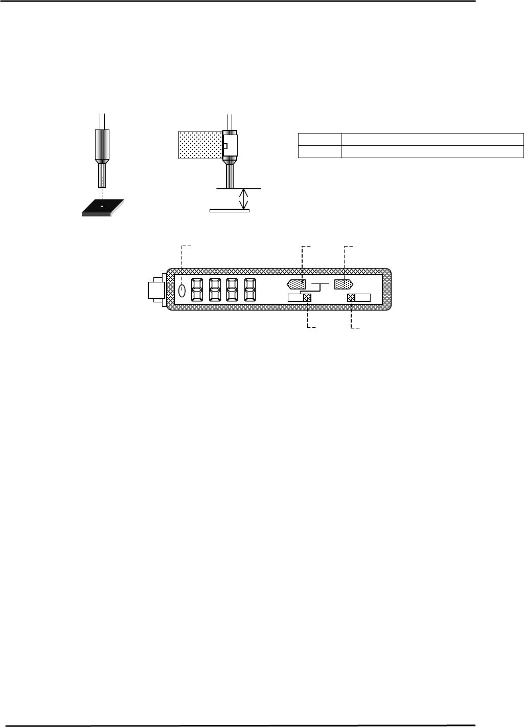
5.15 Loading Position Check Sensor Adjustment
1. At both the IN and OUT loading positions, adjust the bracket so that the loading position check
sensor fiber optic light beam is centered over the silver area of the dog when the XY-table is at
each loading position. [IN/OUT]
2. Set the clearance between the sensor and the dog to 11.5mm.
<I/O → Standard → IN>
Figure 18
11.5mm
X0BF XY-Table In Loading Position Check
X0DA XY-Table Out Loading Position Check
3. Set the In/Out loading position check sensor amps as follows:
a. The amp should always be set to “L_ON” (1)
TEACH
A
DJ
MODE
SET
RUN
L D
2
3
4
5
Figure 19
1
b. Set switch (2) to SET Æ Press the MODE key for 3 sec. Æ Press the TEACH key 3X to
display Æ F-H5 Æ Set switch (2) back to RUN.
c. Set the display to “light amount” by using the mode button (3). (Press the [MODE] key for
2 seconds and the display will change between “light amount” Æ Percentage Æ
“Analogue”)
d. Write down the “light amount”, when the table is moved 0.5mm (250 pulses) in the X -
direction from the IN-loading position. <Example> When XL is – 220500 pulses: use the
values that are displayed at – 220250 pulses and – 220750 pulses.
e. Move the X-axis back to the XL position. Calibrate the light amount when the table is
moved +/-0.5mm (250 pulses) in the Y-direction. <Example> When YL is 2500 pulses: use
the values at 2250 and 2750 pulses.
f. Choose the largest light amount value from steps 4 & 5. (Displayed on the amp)
g. Set switch (2) to “ADJ”, then set the largest light amount by using the [MODE] and
[TEACH] buttons (4). The [Mode] button increases the value. The [Teach] button
decreases the value. (This sets the threshold level for the sensor amp) Values above the
threshold level, (Sensor ON), Values (Sensor OFF)
h. Set switch (2) to “RUN”.
i. Move the X, Y-axes to the loading position by inching and check that the sensor turns
ON.(LED 5 turns on) Next, move the table more than 0.5mm (250 pulses) and check that
the sensor turns OFF.
j. Leave the display on “light amount”.
Fuji Machine Mfg. Co., Ltd. (Okazaki)
SMT Equipment Quality Assurance Dept.
CS Section
5-10