CP7 training(6.0) (1).pdf - 第59页
FK-9F98-27 CP-7 Series T raini ng T ext for Service Engineers Edition 6.0 Chapter 4. S tation Adjustment [10/28] 4.9 Nozzle Changer Adjustment Follow the procedure below in order to adj ust the Nozzle Change Mechani sm C…

FK-9F98-27 CP-7 Series Training Text for Service Engineers
Edition 6.0 Chapter 4. Station Adjustment [9/28]
8. Set the amplifier mode switch to RUN.
9. Confirm for all shafts that the amplifier display reads 0 when the clutch is correctly engaged at 200
degrees, and 9 when the clutch is NOT correctly engaged.
Note: In some cases, it may be necessary to keep re-tuning the sensor amplifier until you get
results of 0 and 9 for all shafts. If these results cannot be achieved, the clearance between
the clutch underside and the meshing check block may not be enough, or the optical fiber
connections to the amplifier may need trimming with a fiber cutter.
10. Confirm sensor operation using the I/O:
<I/O → Standard → IN>
X03A ST10 NOZZLE CLUTCH ENGAGEMENT CHECK
Fuji Machine Mfg. Co., Ltd. (Okazaki)
SMT Equipment Quality Assurance Dept.
CS Section
4-9
FK-9F98-27 CP-7 Series Training Text for Service Engineers
Edition 6.0 Chapter 4. Station Adjustment [10/28]
4.9 Nozzle Changer Adjustment
Follow the procedure below in order to adjust the Nozzle Change Mechanism Correctly.
There are several items for adjustment.
4.9.1 Alignment
4.9.2 Gear Backlash
4.9.3 Stroke
4.9.4 NC origin Calibration data
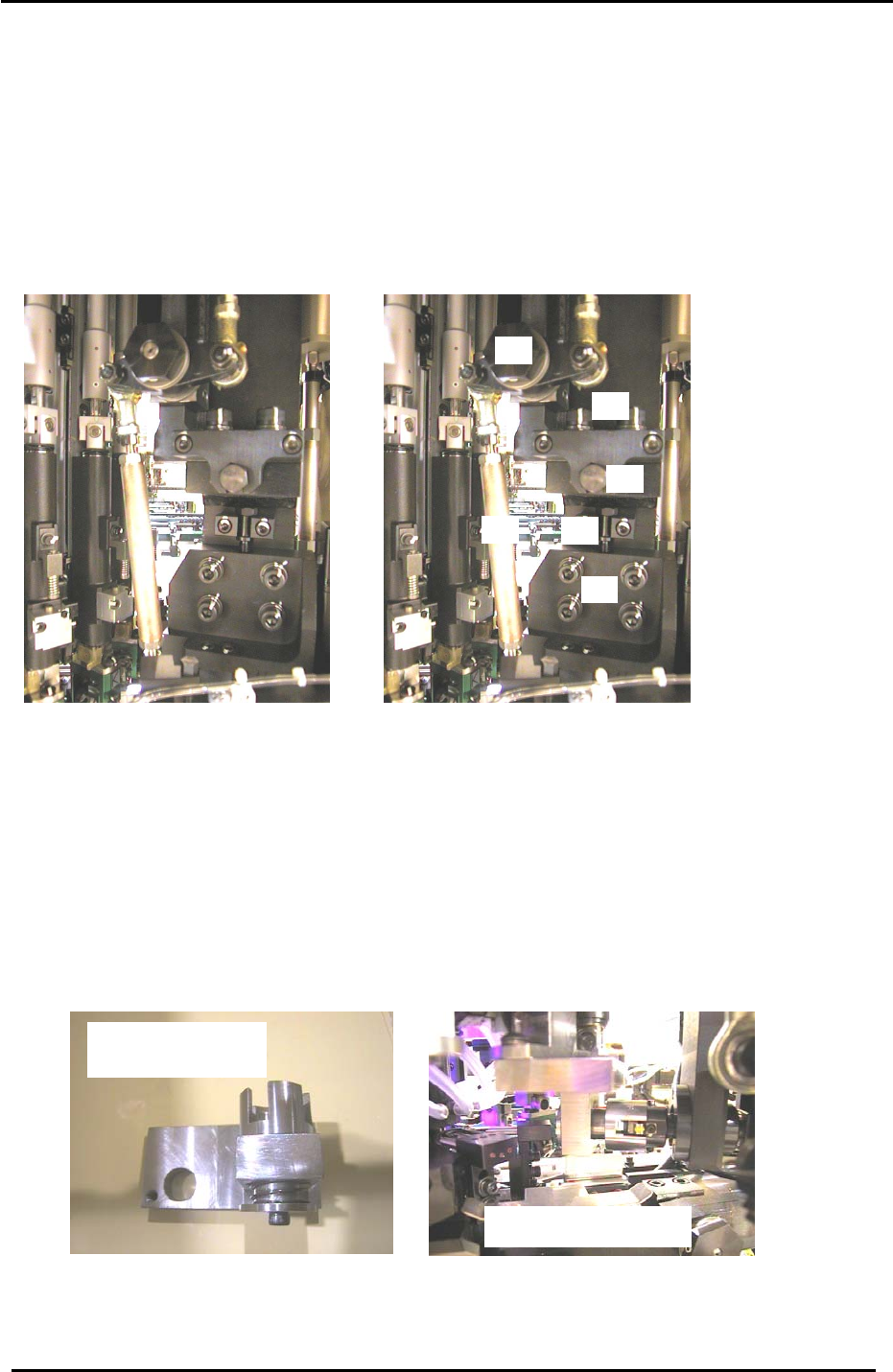
4.9.1 Nozzle Changer Alignment Adjustment
5
2
3
4
6
1
Figure 15
Item 1 = Stroke adjusting rod
Item 2 = UP/DOWN positioning bolts
Item 3 = Height adjusting bolt
Item 4 = Fwd/Bwd adjusting bolt
Item 5 = Fwd/Bwd positioning bolts
Item 6 = N.C intersection lever
1. At 0 degrees, disconnect the air supply to the machine.
2. Remove the cover from the nozzle change drive gears.
3. Turn the 14
th
station nozzle changer solenoid OFF at 0 degrees. (Y036)
4. Move shaft A to the 15
th
station and install the alignment jig.
5. Carefully rotate the jig into the 14
th
station and set the cam at 200 degrees.
Caution: because the jig spans two shafts, never rotate the cam outside of stations 14 and 15.
The N.C alignment check
N.C axis alignment jig
Jig No. ADCPJ8040
Figure 16
6. Confirm that the N.C axis fits smoothly into the jig. If not, adjust by loosening the up/down and
forward/backward positioning bolts and utilizing the adjustment bolts.
Fuji Machine Mfg. Co., Ltd. (Okazaki)
SMT Equipment Quality Assurance Dept.
CS Section
4-10
FK-9F98-27 CP-7 Series Training Text for Service Engineers
Edition 6.0 Chapter 4. Station Adjustment [11/28]
7. Confirm that the N.C intersection lever shown in figure 15 (item 6) is horizontal when the cam is at
0 degrees. Adjust otherwise.
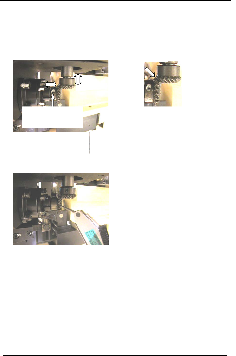
4.9.2 Nozzle Changer Gear Backlash Adjustment
1. Confirm that the two gears where the motor intersects the NC axis are aligned correctly. Then,
lock the 4 small set screws (there are two on each gear):
One of 2 set screws on each
bevel gear. (Ensure the
screws are seated at the
flats on each shaft.
)
Figure 17
2. Turn the servo ON.
3. Place a dial gauge on the lower of the two gears (figure 18) and measure the backlash of the gear
at four points: 0, 90, 180 and 270 degrees. The backlash should be in the range 0.03 to 0.13mm.
If the backlash is not in range, realign the two gears as described in step 1.
Figure 18
4.9.3 Nozzle Changer Stroke Adjustment
1. Turn the servo OFF and attach a nozzle holder to shaft A.
2. Set the 10
th
station RQ to its original position and rotate the A-shaft through the 10
th
station to
make sure the nozzle holder is aligned correctly.
3. Rotate the “A “ shaft with holder attached to the 13
th
station at 0 degrees.
4. Turn ON the 14
th
station, nozzle changer solenoid valve by I/O: [I/O] → [Standard] →
[OUT] → Y037 ST14 NOZ CHANGE SOLENOID ENGAGED.
5. Rotate the A-shaft towards the 14
th
station and just before the nozzle changer clutch engages with
the nozzle holder (at around 130 degrees) place a dial gauge on the nozzle holder as shown in
figure 19 on the following page.
Fuji Machine Mfg. Co., Ltd. (Okazaki)
SMT Equipment Quality Assurance Dept.
CS Section
4-11