CP7 training(6.0) (1).pdf - 第36页
FK-9F98-27 CP-7 Series T raini ng T ext for Service Engineers Edition 6.0 Chapter 3. X, Y , Z and D-axes Adjustm ent [22/36] 1 1. Move the D1-axis back 500 pulses from where the − OT sensor turns ON and set the Calibrati…
FK-9F98-27 CP-7 Series Training Text for Service Engineers
Edition 6.0 Chapter 3. X, Y, Z and D-axes Adjustment [21/36]
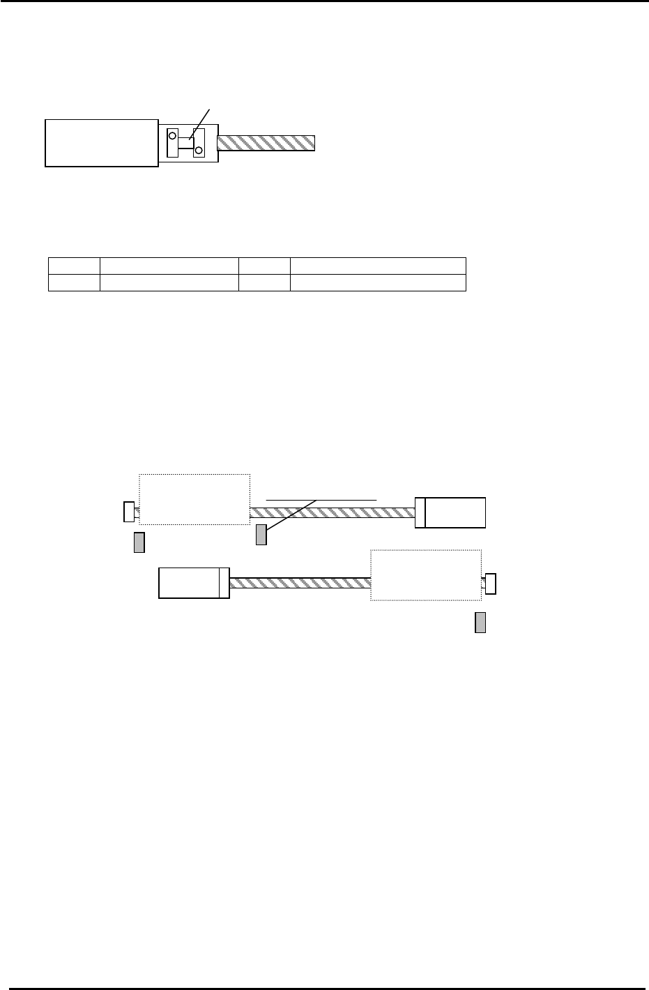
3.12 D-axis Adjustment and Calibration Data Setting
3.12.1 D-axis Adjustment and Calibration Data setting for CP-742/743(M)E and CP-732/733E
Coupling
MOTOR
Figure 27
1. Use the I/O to set the D1 and D2 tables as follows:
<I/0 → Standard → OUT>
Y057 D1 PALLET DOWN Y059 D1 STOPPER UNCLAMP
Y067 D2 PALLET DOWN Y069 D2 STOPPER UNCLAMP
2. To allow access to the D1 coupling, manually move the D2 table towards the center of the D-axis.
3. Check that the coupling is free to move and is centered between the motor and ball screw shafts.
Note: Be careful when handling the coupling as some edges may be sharp!
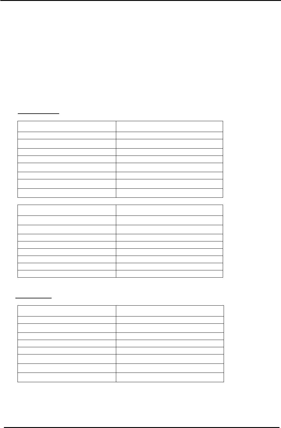
4. Remove the minus OT brackets for D1 and D2.
D1 Motor
D2 Motor
D2 Pallet
− Stopper
+ Stopper
D1 Pallet
−
Stopper
Interference Prevention
Sensor
D1 + OT (SX041)
D2 + OT (SX049)
D1
− OT Sensor
(SX042)
+ Stopper
D2 − OT Sensor
(SX04A)
Figure 28
5. Manually turn the ball screw and set the D1 pulse count to 5000 pulses. (D2: Minus 5000)
6. Pull D1 against the + mechanical stopper. (D2 against the
− mechanical stopper)
7. Half lock the two visible coupling bolts, one on each side of the coupling.
8. Move D1/D2 away from their mechanical stoppers.
9. Lock the four 5mm bolts in rotation with an 8.3N.m torque wrench (CP-742/743(M)E).
For CP-732/733E, use an 8.3N.m torque wrench for the 4mm bolts and a 4N.m torque wrench for
the 3mm bolts.
Be careful to ensure that the coupling is locked equally at all 4 points, i.e. the gaps in the coupling
should be roughly equal.
10. Set the
− OT (D1 / D2) sensors 3500 pulses back from their respective mechanical stoppers.
Check that the OT sensor flag is in the center of the sensor.
Fuji Machine Mfg. Co., Ltd. (Okazaki)
SMT Equipment Quality Assurance Dept.
CS Section
3-21
FK-9F98-27 CP-7 Series Training Text for Service Engineers
Edition 6.0 Chapter 3. X, Y, Z and D-axes Adjustment [22/36]
11. Move the D1-axis back 500 pulses from where the
− OT sensor turns ON and set the
Calibration Data value. (Maximum Limit D1)
Press: [Maintenance] → [Calibration] → [Travel Limits] → [Maximum Limit D1]
To set the Min travel limit for (D2), Move the D2-axis back 500 pulses from where the
− OT
sensor turns ON and set the Calibration Data value. (Minimum Limit D2)
Press: [Maintenance] → [Calibration] → [Travel Limits] → [Minimum Limit D2]
12. The following tables list the D axis Calibration Data and physical data reference values:
CP-742/743ME
D Axis Calibration Data Item (D1) Reference Value (0.002mm/pulse)
+ Mechanical Stopper 5000 +/- 50
− OT Sensor ON
1500 +/- 50
Max Limit Position D1 1000 +/- 50
D1 Original Position 0 +/- 1000
Pick up position T1
(
− 670700)
Minimum Limit Position D1 – 673500 +/- 1000
+ OT Sensor ON
− 674000 +/- 1000
− Mechanical Stopper − 677500 +/- 1000
D Axis Calibration Data Item (D2) Reference Value (0.002mm/pulse)
− Mechanical Stopper − 5000 +/- 50
− OT Sensor ON − 1500 +/- 50
Min Limit Position D2 – 1000 +/- 50
D2 Original Position 0 +/- 1000
Pick up position T2 (351300)
Max Limit Position D2 673500 +/- 1000
+ OT Sensor ON 674000 +/- 1000
+ Mechanical Stopper 677500 +/- 1000
CP-732/733E
D Axis Calibration Data Item (D1) Reference Value (0.002mm/pulse)
+ Mechanical Stopper 5000 +/- 50
− OT Sensor ON
1500 +/- 50
Max Limit Position D1 1000 +/- 50
D1 Original Position 0 +/- 1000
Pick up position T1 (-504700)
Minimum Limit Position D1
− 507000 +/- 1000
+
OT Sensor ON
− 507500 +/- 1000
− Mechanical Stopper − 508500 +/- 1000
Fuji Machine Mfg. Co., Ltd. (Okazaki)
SMT Equipment Quality Assurance Dept.
CS Section
3-22
FK-9F98-27 CP-7 Series Training Text for Service Engineers
Edition 6.0 Chapter 3. X, Y, Z and D-axes Adjustment [23/36]
CP-732/733E
D Axis Calibration Data Item (D2) Reference Value
(0.002mm/pulse)
− Mechanical Stopper − 5000 +/- 50
− OT Sensor ON − 1500 +/- 50
Min Limit Position D2
− 1000 +/- 50
D2 Original Position 0 +/- 1000
Pick up position T2 (264300)
Max Limit Position D2 507000 +/- 1000
+ OT Sensor ON 507500 +/- 1000
+ Mechanical Stopper 508500 +/- 1000
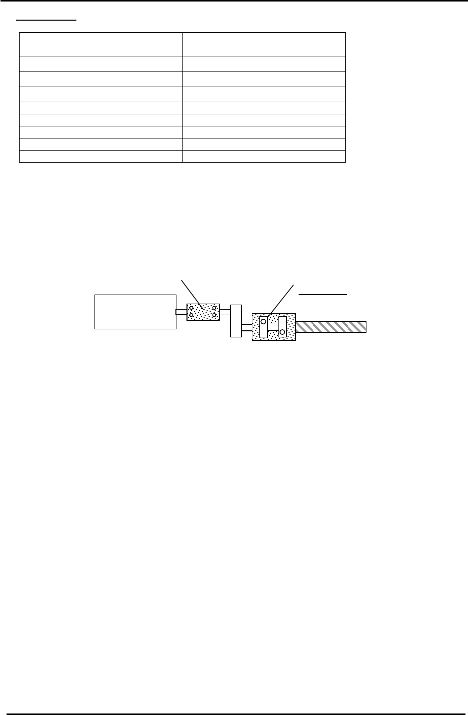
3.12.2 CP-742/743E Supplementary Procedure
The method of locking the coupling is slightly different on the CP-742/743E and is described
below. For the basic procedure, please refer to section 3.12.1.
Coupling 2
MOTOR
Coupling 1
Figure 29
1. Ensure that the D table is against the mechanical stopper.
2. Lock the two right hand bolts of Coupling 1 with an 8.3N.m torque wrench and long 5mm
attachment.
3. Lock the two left hand bolts of Coupling 2 with a 67.6N.m torque wrench and 10mm
attachment.
4. Lock the two left hand bolts of coupling 1 with an 8.3N.m torque wrench and long 5mm
attachment.
5. Rotate Coupling 2 by hand until the pulse count is 5000 pulses (D1). – 5000 pulses (D2).
6. Turn the servo ON.
7. Finally, Lock the two right hand bolts of Coupling 2 with a 67.7N.m torque wrench and 10mm
attachment.
Fuji Machine Mfg. Co., Ltd. (Okazaki)
SMT Equipment Quality Assurance Dept.
CS Section
3-23