CP7 training(6.0) (1).pdf - 第64页
FK-9F98-27 CP-7 Series T raini ng T ext for Service Engineers Edition 6.0 Chapter 4. S tation Adjustment [15/28] 4.12 St ation 1 W aste T ape Cutter Adjustment 1. Set the cutter rod length in the cam box to 21mm. 21mm 2.…
FK-9F98-27 CP-7 Series Training Text for Service Engineers
Edition 6.0 Chapter 4. Station Adjustment [14/28]
12. Check that the sensors react correctly when the nozzle holder is set to the positions shown in
the following table:
Sensor 1 Sensor 2 Sensor 3
Nozzle No. 1 8 ~ 9 (ON) 0 ~ 1 (OFF) 0 ~ 1 (OFF)
Nozzle No. 2 0 ~ 1 (OFF) 8 ~ 9 (ON) 0 ~ 1 (OFF)
Nozzle No. 3 0 ~ 1 (OFF) 0 ~ 1 (OFF) 8 ~ 9 (ON)
Nozzle No. 4 8 ~ 9 (ON) 8 ~ 9 (ON) 0 ~ 1 (OFF)
Nozzle No. 5 0 ~ 1 (OFF) 8 ~ 9 (ON) 8 ~ 9 (ON)
Nozzle No. 6 8 ~ 9 (ON) 0 ~ 1 (OFF) 8 ~ 9 (ON)
<I/O → Standard → IN>
Sta. 13 X03E Nozzle Type Check 1 X03F Nozzle Type Check 2
Sta. 15 X048 Nozzle Type Check 1 X049 Nozzle Type Check 2
Sta. 13 X040 Nozzle Type Check 3
Sta. 15 X04A Nozzle Type Check 3
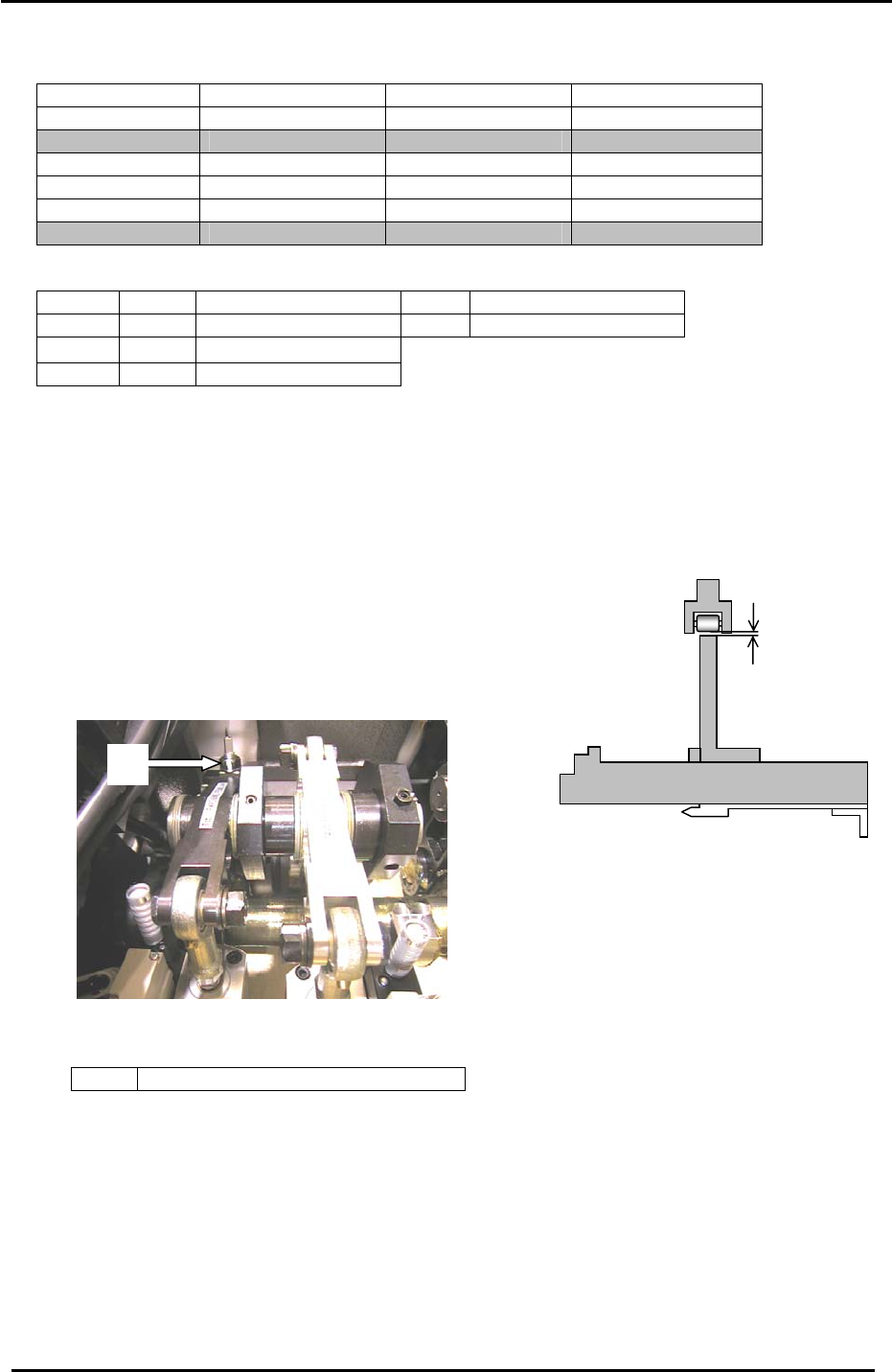
4.11 Station 1 Tape Feed Adjustment
1. Set the cam angle to 0 degrees, turn the station 1 tape feed
solenoid valve ON. (Y033)
2. Move the jig to the parts pick-up position. Adjust the
clearance between the roller and the lever to 0.5mm.
To adjust loosen bolt “A” in the cam box, (figure 22) and
then use a small spanner to adjust the rod up or down.
<I/O → Standard → OUT>
Jig No. ADCPJ8020
0.5mm
A
Figure 22
Y033 ST1 TAPE FEED SOL ENGAGED
Fuji Machine Mfg. Co., Ltd. (Okazaki)
SMT Equipment Quality Assurance Dept.
CS Section
4-14
FK-9F98-27 CP-7 Series Training Text for Service Engineers
Edition 6.0 Chapter 4. Station Adjustment [15/28]
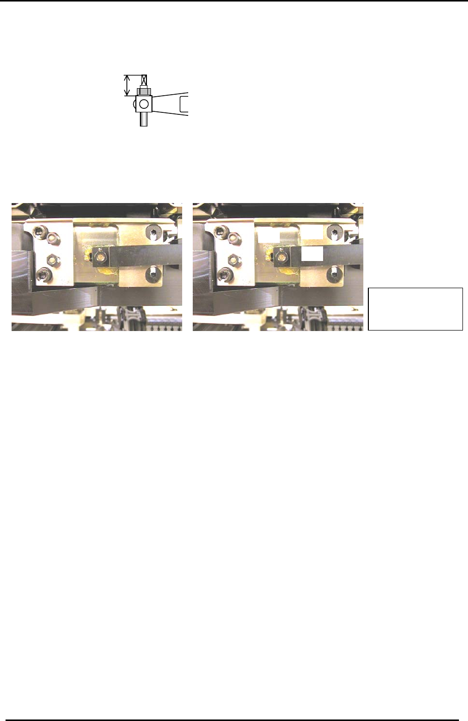
4.12 Station 1 Waste Tape Cutter Adjustment
1. Set the cutter rod length in the cam box to 21mm.
21mm
2. Use a feeler gauge to check that there is more than 0.2mm clearance between the cutter
lever and guard:
1
3
2
Item 1 = Cutter Lever
Item 2 = Guard
Item 3 = Cutter Tooth
Figure 23
3. Check that the tape cutter does not protrude from the guard at 0 degrees.
4. Check that the tape cutter rises up until (190 degrees, CP-742/743(M)E) (194 degrees, CP-
732/733E) and descends afterwards.
5. Check that the tape cutter is level with the bottom of the guard (or protrudes by less than
0.5mm from the bottom of the guard) at 0 degrees.
6. Use a tape feeder to confirm that the tape cutter can actually cut the tape on a feeder.
Fuji Machine Mfg. Co., Ltd. (Okazaki)
SMT Equipment Quality Assurance Dept.
CS Section
4-15
FK-9F98-27 CP-7 Series Training Text for Service Engineers
Edition 6.0 Chapter 4. Station Adjustment [16/28]
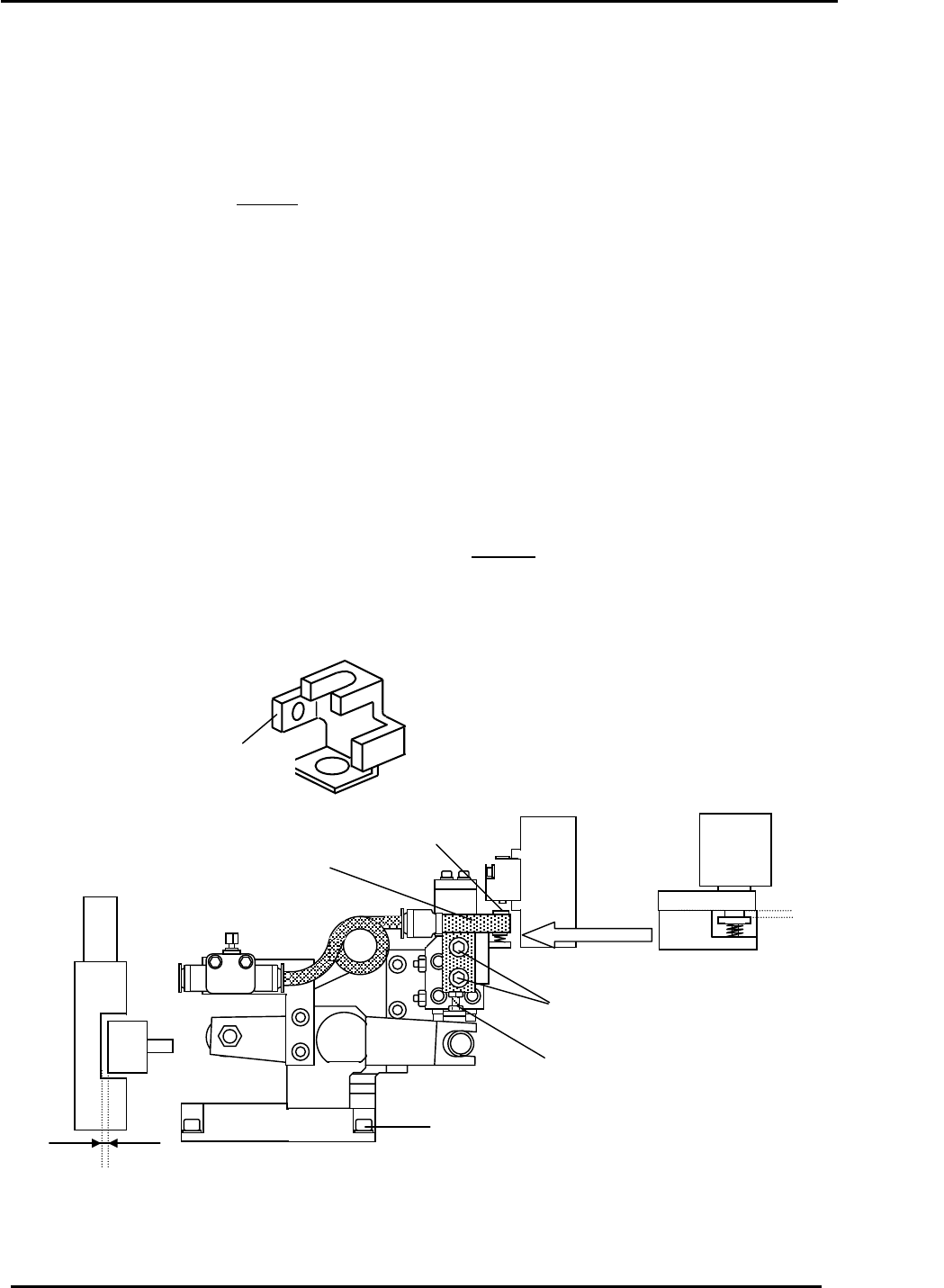
4.13 Station 13 Parts Reject Mechanism Adjustment
1. Remove the 13
th
station valve switch bracket and check the clearance at the top and bottom of
the LM guide. Tolerance: > 0.5mm.
2. Loosen the 4 mounting bolts at the base of the 13
th
station bracket.
3. Rotate the shaft with the
Highest valve (measured in 3.16) to station 12 and install the unit
alignment jig over the valve. Reattach the valve switch bracket, leaving the bolts slightly loose.
4. Carefully, rotate the shaft into station 13 at 190 degrees (CP-742/743(M)E), (194 degrees CP-
732/733E) and align the valve lever and jig by moving the mounting bracket.
5. After positioning the valve switch bracket inside the jig hole, tighten the 4 mounting bolts at the
base of the 13
th
station.
6. The clearance between the cam follower and drive lever should be 0.2mm or more. If less than
0.2mm, loosen the mounting bracket for the cutter assembly and move slightly to set the proper
clearance.
7. Loosen the height adjusting bolts and use a feeler gauge to set the gap shown in figure 24 to
0.3mm. Use the height adjustment bolt to set the gap.
8. Set the flow controller as follows: For rough adjustment of the flow controller, set 4 turns from
fully closed. For fine adjustment, set the shaft with the
highest valve at station 13 and set the
cam as described in step 4. [Turn ON (I/O Y03A)] Using a manometer, set the air pressure to
52+/-3mmHg. (7.0+/-0.5 kPa)
Unit alignment jig
Jig No.: Z9627DGPJ0110
0.3mm gap
Valve
Valve switch BKT
Pusher
A
djustment bolt
4 x mounting bolts
Figure 24
Valve switch mounting bolts
Cam followe
r
> 0.2mm
Fuji Machine Mfg. Co., Ltd. (Okazaki)
SMT Equipment Quality Assurance Dept.
CS Section
4-16