3OM-1343-008_w.pdf - 第117页
3-32 AKFEDT -ID 1.2.5 (A04) Setup Data Note Unless "Enable" is selected for a device to be set up, the machine does not perform any setup operation on the device. (A04_01) Conveyor "Enable" or "D…
3-31
AKFEDT-ID
(2) Material for Marks
Copper Leaf
Nickel Plating
Solder Plating
Solder Leveler
Gold Plating
Note
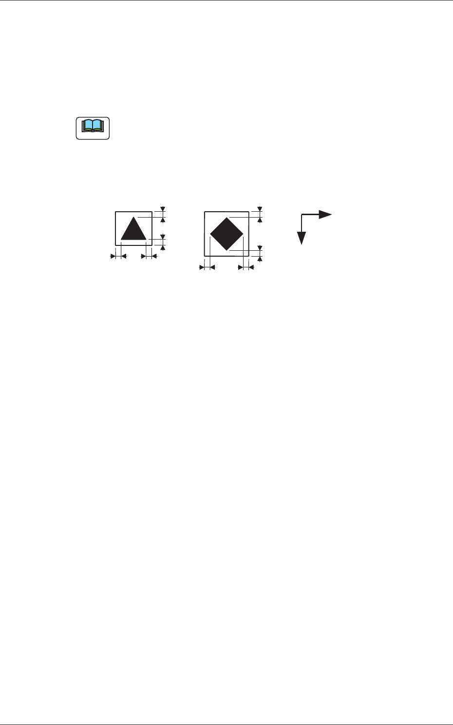
(a) A copper leaf, a resist, a coating, a silk print, and a punched hole
should not exist in the range of 1.0 mm in both X and Y directions
from the outermost edges of a fi ducial mark. They may cause false
recognition.
Example:
1.0
1.0
1.0
1.0
1.0
1.0
1.0
1.0
Y
X
(Front Side of Machine)
Unit: mm
Fig. 3C25
(b) The shape of PCB (a cutout, a punched hole), the external elements
(light refl ected from a structure, light emitted from an external device,
etc.) may sometimes interfere with recognition of fi ducial marks.
(c) A fi ducial mark should make ample contrast with the surroundings.
(To prevent false recognition)
(d) Anything resembling a pattern similar to a fi ducial mark should not
exist in the designated recognition window. If one exists, it may cause
false recognition.
(e) A test may be required when the fi ducial mark cannot be recognized
because of the extreme warpage of the PCB.
0601-002
1.2 Operation Data

3-32
AKFEDT-ID
1.2.5 (A04) Setup Data
Note
Unless "Enable" is selected for a device to be set up, the machine does not
perform any setup operation on the device.
(A04_01)
Conveyor
"Enable" or "Disable" can be selected to determine whether the
conveyor width should be set up or not after a program change
operation.
Disable :
The conveyor width setup operation is not performed.
Enable :
The conveyor width setup operation is performed.
(A04_02)
PCB Y Position Arrangement
It can be determined whether or not the PCB transfer section should
be moved in the optimum Y direction according to the pattern program
when a program change operation is performed.
Mode
Select either "Enable" or "Disable" in the "Mode" text box of the label
"PCB Y Position Arrangement".
Disable :
The Y position of the PCB is not arranged.
Enable :
The Y position of the PCB is arranged.
Specify Method
When "Enable" is set in the "Mode" text box, select one of the
following options.
Specifi ed Position :
The conveyor Y position in the PCB
positioning section is moved to the
specifi ed position.
Base Conveyor Fixation :
The PCB positioning section is fi xed to
the reference position.
Position [mm]
When "Specifi ed Position" is set in the "Specify Method" text box,
specify the distance of the PCB Y position (center) to be shifted from
the machine’s positioning center.
0604-003
1.2 Operation Data

3-33
AKFEDT-ID
1.3 Placement Head/Nozzle Data
(B01_01)
Head 1, 2, 3, and 4
Nozzle 1 through 12, ID Names
This data is used to allocate the nozzles to the specifi ed positions (Nozzle
Allocation Nos.) on the heads.
0601-002
1.3 Placement Head/Nozzle Data