3OM-1343-008_w.pdf - 第96页
3-1 1 AKFEDT -ID Bottom [mm] When PCBs with some components already mounted on the lower surfaces (back) by the input machine are transferred to this machine, be sure to enter the thickness of the highest component in th…
3-10
AKFEDT-ID
0601-002
(A01_08)
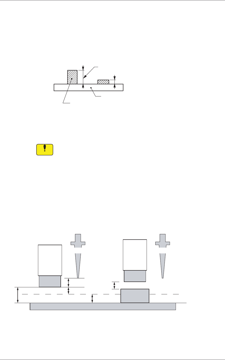
Pre-Placed component thickness
Top [mm]
When some components are placed previously on a PCB by the input
machine, etc., and transferred to the main machine, be sure to enter the
thickness of the tallest component of all in the text box.
Tallest Previously-Placed Component
Set this thickness in the text box.
PCB
Fig. 3C12
•
Data Input Range
0 to 12.700
Notice
(a) When components are placed previously and the main machine
is operated with
"
0.00
"
in this text box, some of the previously-
placed components may interfere with components to be
placed newly.
(b) It is advisable that placement data should be created such that
shorter components are placed before the tallest one.
(c)
When the specifi ed thickness of a previously-placed
component differs from the actual one, the light emitter of the
linear measure sensor may interfere with the previously-placed
component.
3.0 mm
5.0 mm
2.0 mm
3.0 mm
2.0 mm
No Previously-Placed Component
Previously-Placed Component
NL Origin Position NL Origin Position
Light
Emitter
Light
Emitter
Previously-
Placed
Component
PCB
Placement Level
Fig. 3C13
1.2 Operation Data
3-11
AKFEDT-ID
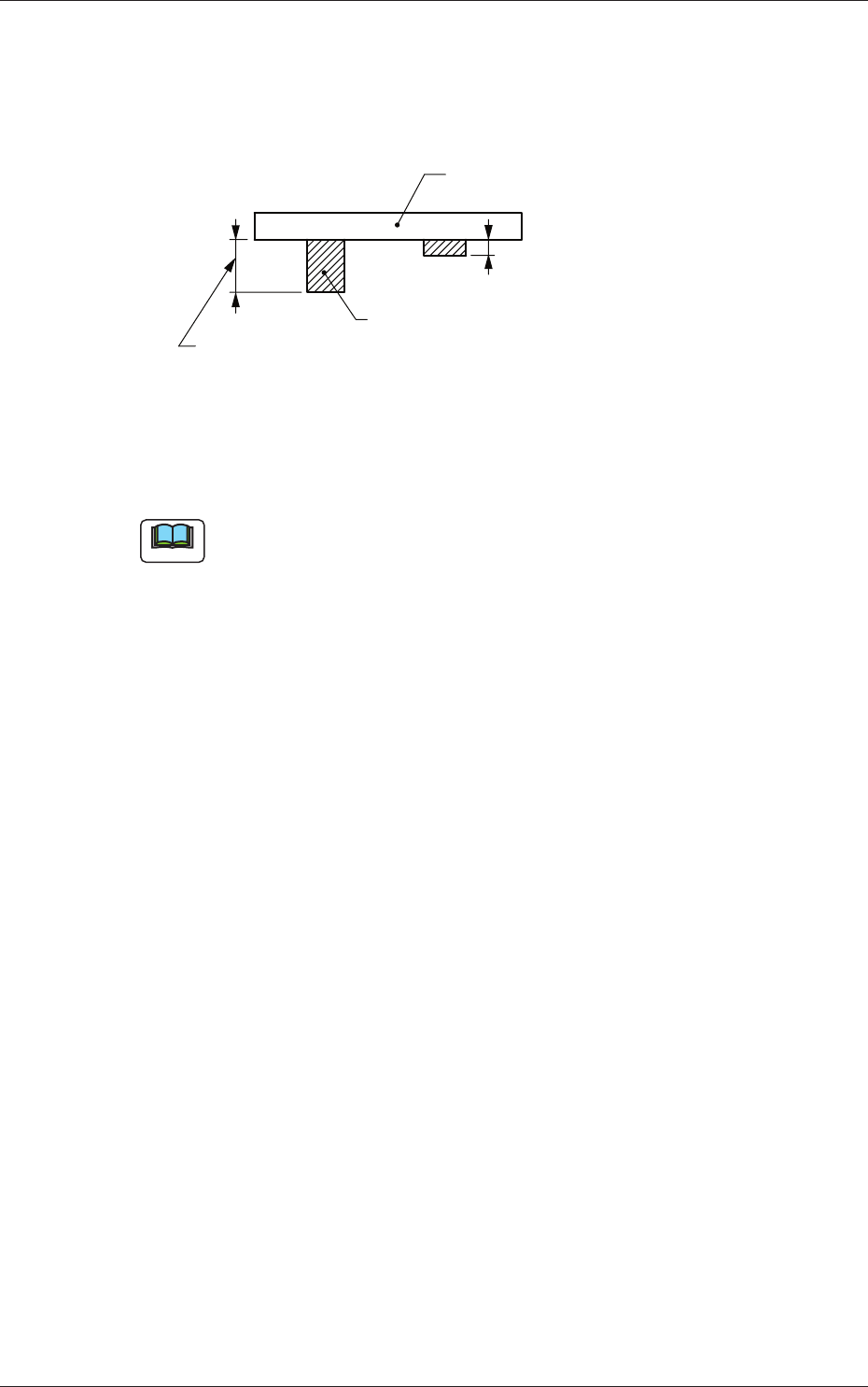
Bottom [mm]
When PCBs with some components already mounted on the lower
surfaces (back) by the input machine are transferred to this machine, be
sure to enter the thickness of the highest component in the text box.
Tallest Previously-Placed Component
PCB
Set this thickness in the text box.
Fig. 3C14
• Data Input Range
0 to 30.000
Note
(a) The set parameter is used to determine the position (elevation) of the
fi rst backup table when the PCB is transferred to the PCB positioning
section.
(b) When components are placed previously and the main machine is
operated with "0.00" (no previously-placed components) in this text
box, the support pins may interfere with some of the previously-
placed components on the back of PCB while the PCB is being
transferred to the PCB positioning section.
(A01_09)
PCB transfer speed
Input, Between Stages, Output
Select one of the following options as PCB transfer speed.
Standard :
PCBs are transferred at normal speed.
Low Speed 1 :
PCBs are transferred at a speed slower than
"
Standard
"
.
Low Speed 2 :
PCBs are transferred at a speed slower than
"
Low Speed 1
"
.
Low Speed 3 :
PCBs are transferred at a speed slower than
"
Low Speed 2
"
.
Specifi cation Value :
Your desired speed can be specifi ed.
0601-002
1.2 Operation Data

3-12
AKFEDT-ID
(A01_10)
PCB transfer speed des
When "Specifi cation Value" is set in "(A01_09) PCB transfer speed", it
is required to specify the following items.
Avoid comp deviation
Input, Between Stages, Output
Set one of the following options in each text box.
Speed 1 [mm/sec]
PCBs are transferred at the specifi ed speed.
Speed 2 [mm/sec]
The PCB being transferred at "Speed 1" is detected by the
deceleration sensor and the transfer speed decreases to the
specifi ed one.
Acceleration [G]
Set the acceleration value to reach the speed specifi ed in "Speed
1 [mm/sec]".
Stop position control
Input, Positioning 1, Center, Positioning 2, Output
Set one of the following options in each text box.
Timer [msec]
Specify the time during which the transfer speed of the PCB
detected by the deceleration sensor is decelerated to "Speed 2
[mm/sec]".
•
Default:
350 [mm/sec]
Position [mm]
Specify the distance of the PCB transfer between the time when
the PCB was detected by the stop sensor and the time when the
PCB was stopped.
0601-002
1.2 Operation Data