3OM-1343-008_w.pdf - 第152页
3-67 AKFEDT -ID (2) Creation of Operation Data • PCB Data T able 3C5 PCB size X (Horizontal) [mm] 330.000 Y(V ertical) [mm] 250.000 T(Thickness) [mm] 1.600 PCB X( Horizontal) [mm] +0.000 origin offset Y (V ertical) [mm] …
3-66
AKFEDT-ID
•
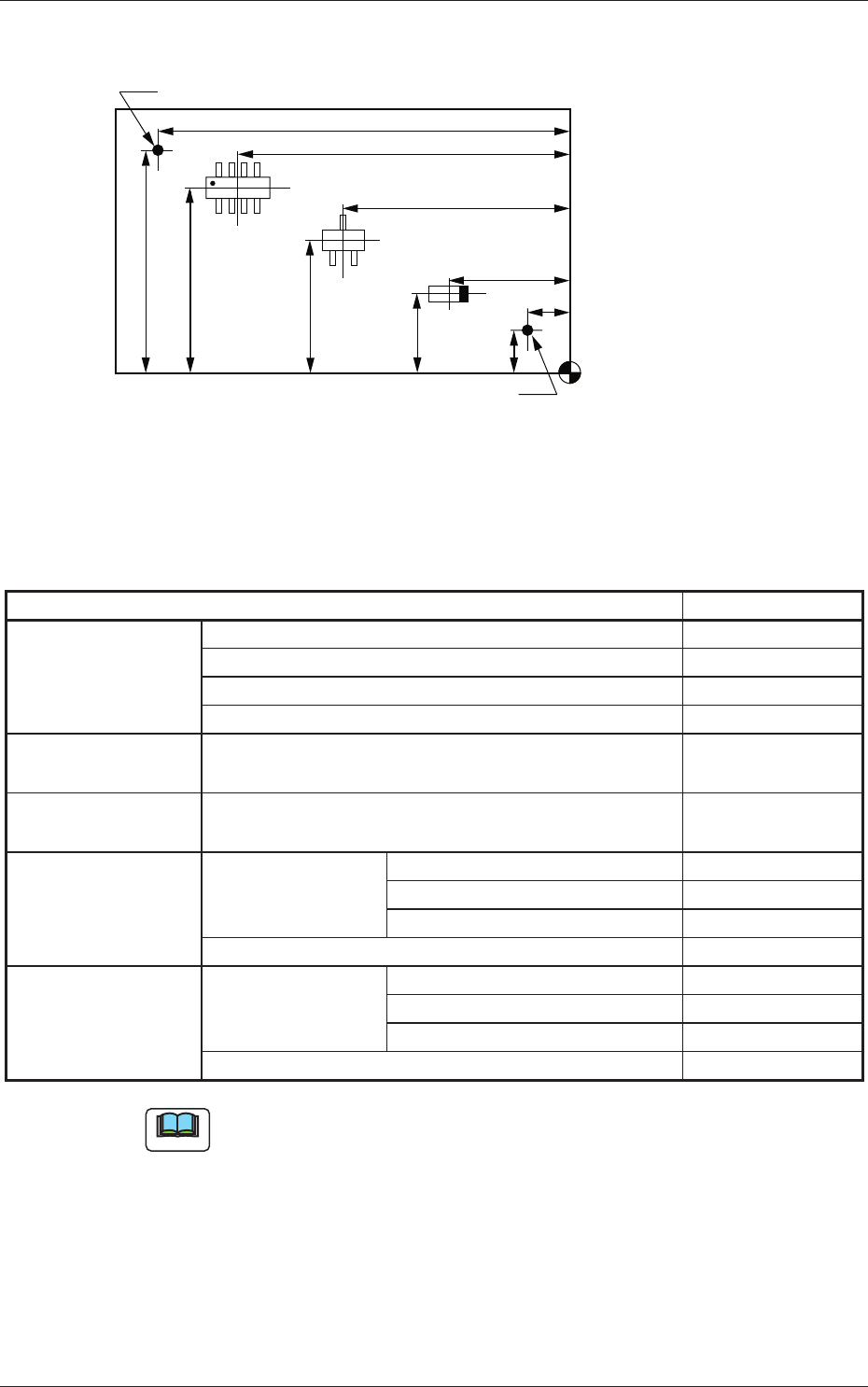
Placement Coordinates, Angles, and Fiducial Mark Coordinates
X3
Y3
X2
Y2
X1
FX1
Y1
FY1
FY2
FX2
Placement Coordinate
Reference
Fiducial Mark
Fiducial Mark
Fig. 3C53
•
List of Required Data
Table 3C4
Pattern Program Required Data
Operation Data PCB Data
PEC Recognition Data
PEC Recognition Mark Data
Setup Data Note (a)
Placement
Head/Nozzle Data
Heads 1 through 4
Placement Feeder
Location Data
Feeder Bases #1 through #4
Placement Data U01 P-data P-data
Unit Control Note (b)
Unit PCB Fiducial ×
O-data
×
Placement Data Un P-data P-data ×
Unit Control ×
Unit PCB Fiducial ×
O-data ×
Note
(a) Create this data for automatic conveyor width adjustment.
(b) Specify these parameters (data) according to the situational changes.
0601-002
3.1 Single Pattern (Global Recognition Enabled)

3-67
AKFEDT-ID
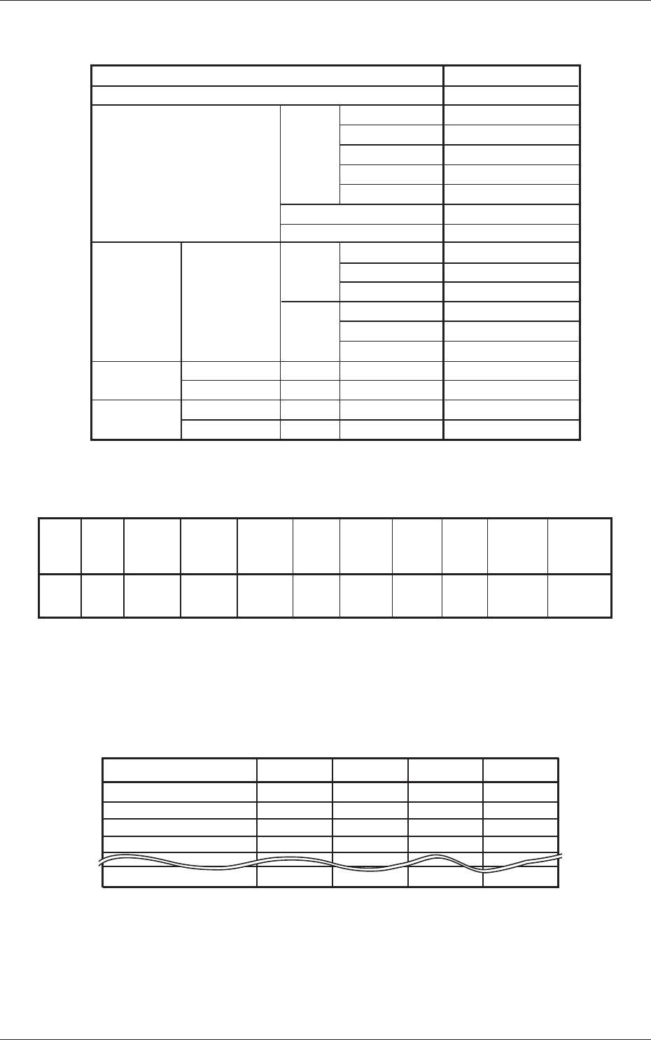
(2) Creation of Operation Data
•
PCB Data
Table 3C5
PCB size X (Horizontal) [mm] 330.000
Y(Vertical) [mm] 250.000
T(Thickness) [mm] 1.600
PCB X(Horizontal) [mm] +0.000
origin offset Y (Vertical) [mm] +0.000
Z (deg) [o] +0.00
XY-Angle [deg] [o] +0.00
X-Direction Same
Y-Direction
Z Angular Orientation
PCB height offset [mm] +0.000
Placement Reference
Front Right
PCB locate Sequence
Standard
PCB transfer Sequence
Output Priority
Pre-Placed component Top [mm] 0.000
thickness Bottom [mm] 0.000
PCB transfer speed Input
Between Stages
Output
Input Conveyor Y Position arrange speed setup
(% deceleration)[%]
0
0
PCB locate mode Stage 1 Operation
Std
Stage 2 Operation
Std
Placement mode Stage 1
Placement
Stage 2 Pass
Recovery regulation U-N Stage 1
Disable
Stage 2
Block Sort
Same
Same
Standard
Standard
Standard
Output Conveyor Y Position arrange speed setup
(% deceleration)[%]
Stage 1
Stage 2
Disable
Disable
Disable
0601-002
3.1 Single Pattern (Global Recognition Enabled)
3-68
AKFEDT-ID
•
PEC Recognition Data
Table 3C6
PEC recognition function Enable
Correction algorithm Standard
Zone 1 2 Point
Zone 2 Disable
Zone 3 Disable
Zone 4 Disable
Zone 5 Disable
Image Disable
local Disable
Fiducial Zone 1 #1 X (Horizontal) FX1
mark Y (Vertical) FY1
Mark Code 1
#2 X (Horizontal) FX2
Y (Vertical) FY2
Mark Code 1
Beam Stage 1 Automatic (1 or 2)
Stage 2 Automatic (3 or 4)
Sequence Stage 1 After Pick Up
Stage 2 After Pick Up
PEC recognition Mode Global
•
PEC Recognition Mark Data
Table 3C7
Mark
No.
Mark
Size
D1[mm]
1 Round 1.00 0.00 0.00 000.00 05.0 Bright High Standard Standard
(Normal)
Mark
Type
Mark
Size
D2[mm]
Mark
Size
D3[mm]
Angle
[deg]
Window
Size
[mm]
Mark
Image
Mark
Level
Lighting
Level
Coax
Lighting
Level
Ring
•
Setup Data
Create this data when the automatic setup function is used.
(3) Creation of Placement Head/Nozzle Data
Table 3C8
Nozzle No. Head 1 Head 2 Head 3 Head 4
Nozzle 1 ID Name
Nozzle 2 ID Name
Nozzle 3 ID Name
Nozzle 4 ID Name
Nozzle12 ID Name
HA04
HV03
HA05
HA04
HV03
HA05
HA04
HV03
HA05
HA04
HV03
HA05
0601-002
3.1 Single Pattern (Global Recognition Enabled)